Tailstock DRO
 |  |
The M250 has graduations on the hand-wheel of the tailstock as well as on the barrel. This can be very useful for drilling holes to a particular depth, but the tailstock lead-screw is 2.5 mm pitch so it is a lot less convenient than one with a round number of millimetres per turn. Also, while it is easy to zero the hand-wheel dial, it is obviously not possible to zero the graduations on the barrel.
An Aside: Measuring Tools
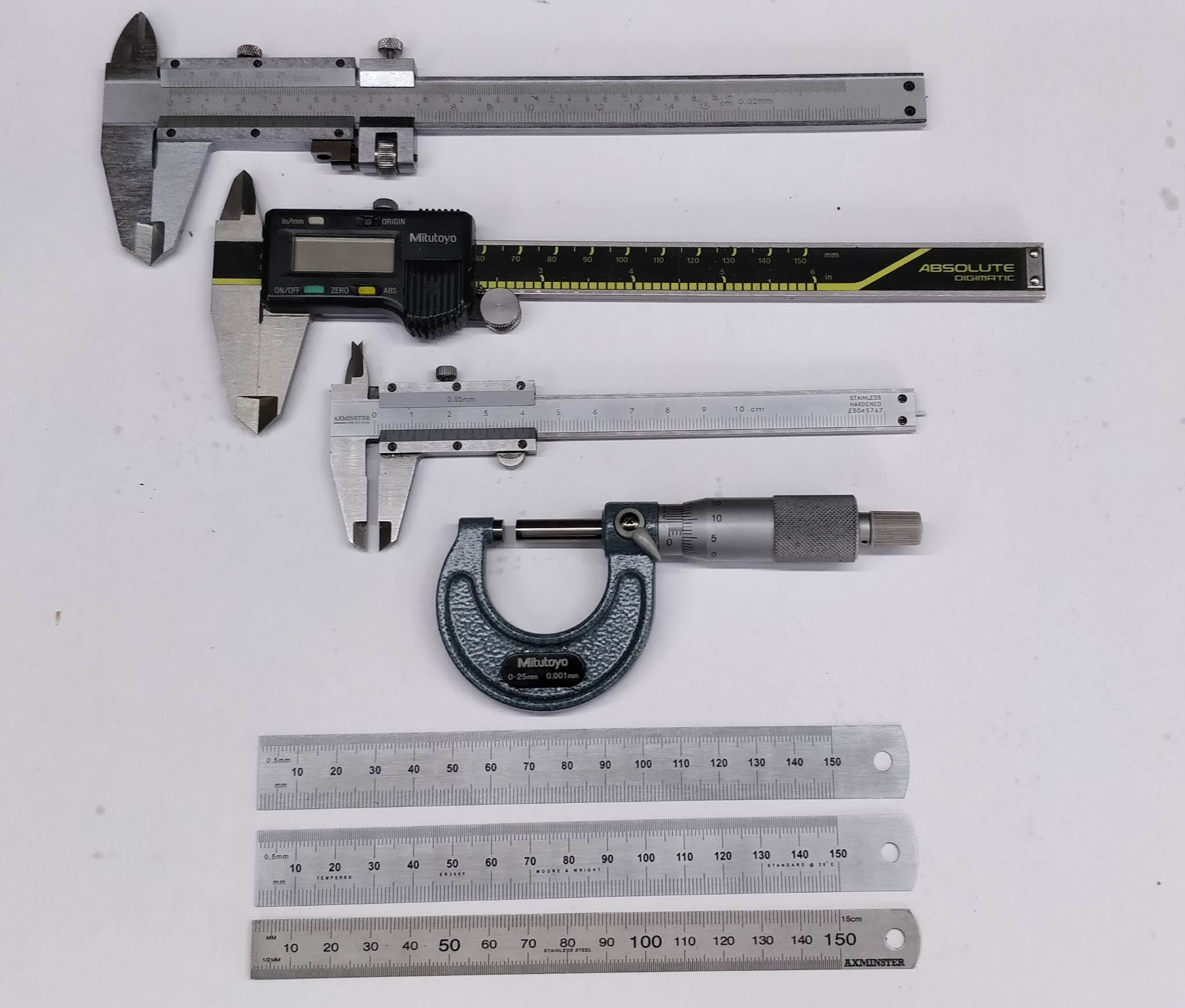 |
I had a few different calipers in periodic use. The one I use 90% of the time is an Axminster 100 mm Pocket Vernier Caliper (third one down in the photo). This only reads to the nearest 0.05 mm (50 μm, but for most of my use this is ample and the small size of the caliper makes it very convenient. Where precision is required, the 1 μm reading Mitutoyo micrometer (with a vernier scale in addition to the normal micrometer scale - fourth one down in the photo) comes out of the drawer. Neither of these are digital and hence I never have to worry about batteries running out or zero-positions having drifted (give or take a very infrequent check just to be sure).
A few years ago I bought a cheap digital caliper (not shown in the picture above). These are available from a number of different suppliers, typically for less than £20. They use an incremental (i.e. keeping track of position continuously and losing position if the battery goes flat) capacitative scale. If you move them quickly when powered off (but with a battery) they have to track this movement, so they never properly shut down. As a result, the batteries don't tend to last long and with my relatively infrequent use I was finding that I needed to change the battery pretty much every time I used the caliper. As a result of all that, it didn't get used much.
I've since bought a second-hand Mitutoyo Absolute Digital Caliper (second in the photo above), which is much higher quality and has an absolute (rather than incremental) scale and hence doesn't suffer from these problems. This is shown in the picture above. Having said that, I still use the 100 mm vernier-scaled one more than the digital one, just the ratio is probably 60:40 now.
Also shown in the picture are a couple of Moore & Wright ER306F 150 mm steel rules and an Axminster one. The two M&W steel rules are shown opposite ways up. I've been searching for a long time for a genuinely useful metric-only steel rule. Unfortunately, a carefully thought out one doesn't seem to exist. If someone at Moore & Wright had actually thought about the use of this ruler when they made it, they might have swapped the scales on each side. If you look closely at the image above (like all photos on this site, you can click on them for a better view), you'll see that on both sides of the steel rule, the bottom edge has 1 mm graduations and the top edge has 0.5 mm graduations. I really don't understand why they didn't swap these round on one of the sides. Even more frustratingly, the photo on the website from which I bought them shows them with swapped layouts exactly as I'd hoped they'd be.
On the Axminster one, rather than having a swapped layout on the rear, they put a conversion table between inches and millimetres. Please can someone at Axminster explain to me why they think I'd go to the effort of searching for a metric-only ruler but want an imperial conversion table on the back (which is way more difficult to use for imperial than just getting a metric/imperial ruler)?!
Rant over, but please do let me know if you come across a proper metric-only 150 mm steel rule.
Back to the Tailstock DRO
As a result of my experiences with a collection of different linear measurement devices, I had a cheap digital caliper that I was pretty much guaranteed never to use. Therefore, I decided to hack it up and turn it into a tailstock DRO, which would be likely to be used far more often and hence hopefully be slightly less wasteful in terms of batteries!
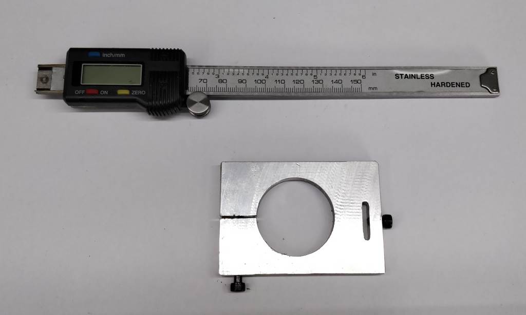 |  |
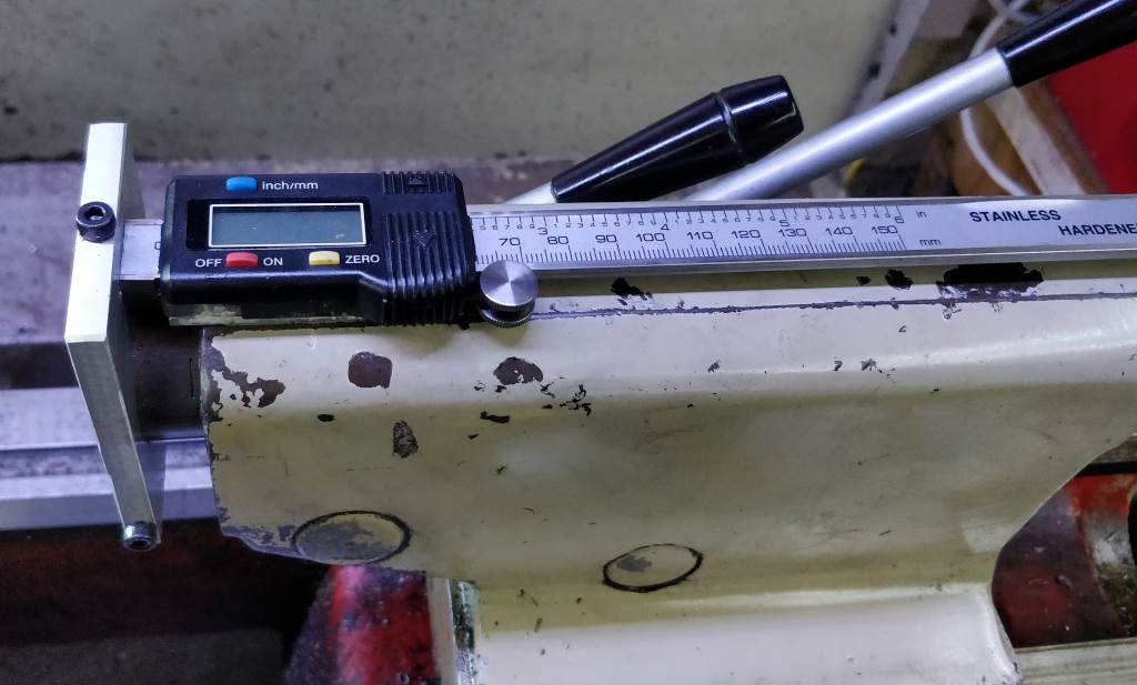
These photos show the parts that make up the DRO. The large plate is 55 mm × 80 mm × 7 mm aluminium. The slot at the top is 4 mm × 18 mm (and accepts the sliding part of the caliper). As is obvious from the photo, the jaws of the caliper have been cut off (with a Dremel) and ground relatively flush (with a bench grinder). The clamping slot at the bottom (left in the photo) is 1 mm wide and is used to hold the plate on the end of the tailstock barrel, as shown in the photo at the top of the page. Both the tailstock barrel clamping screw and the caliper clamping screw are M4.
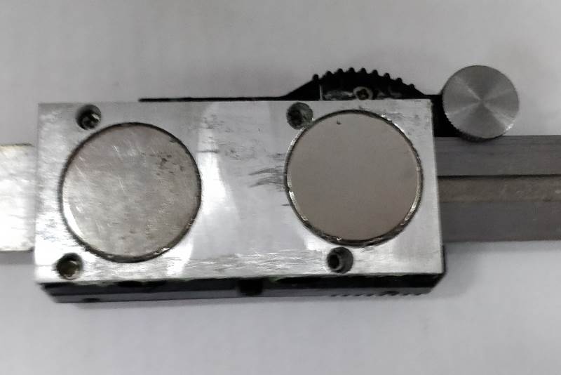 |
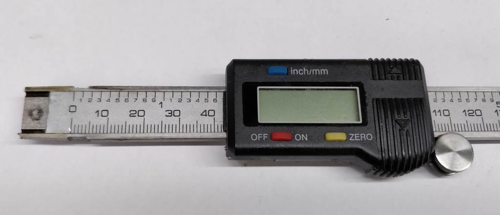
This (terrible quality, sorry) photo shows the rear of the caliper body. I have fitted a 3 mm thick aluminium plate to the back of the body. It has small holes located over the screws that hold the caliper body together and large holes for two 20 mm × 3 mm NdFeB magnets (positioned arbitrarily such that they don't get in the way of the screws. The plate and the magnets are held in place with superglue. The magnets hold the caliper body to the tailstock body and saved me from having to make holes in this casting.
This website is free, but costs me money to run. If you'd like to support this site, please consider making a small donation or sending me a message to let me know what you liked or found useful.