Honing Guide Protrusion Calculator
This tool can be used to calculate the amount of protrusion needed to get a given bevel angle using a honing guide. It supports different honing guides, although if your honing guide isn't listed then you'll have to take some measurements of the guide in order to use it. If you'd like your honing guide to be added to this page, please send me the required dimensions of your guide as described below.
For some honing guides (including the Eclipse style), the thickness of the blade fitted into the plane iron jaws has an effect on the angle. When the Eclipse jig was originally designed, most blades were about 2.1 mm thick, so this variation didn't really matter. With thicker blades from bevel-up tools, it can make a difference to the honing angle you get. Of course, in practice the different angles you get probably doesn't really matter for real-world woodwork, but I found it interesting to understand the effects (and I'm probably slightly unusual in that I enjoy maths). This is explained in more detail below.
| Honing Guide Type: | |||
| Wheel Diameter (mm): | mm | ||
| Reference Face Offset (mm): | mm | ||
| Protrusion Offset (mm): | mm | ||
| Reference Face is Protrusion Face: | |||
| Tool Thickness (mm): | mm | ||
| Bevel Angle (°): | ° | ||
| Tool Protrusion (mm): | mm | ||
† Note that the offsets for the Veritas Mk2 Honing Guide do not take into account the position of the eccentric roller (but then neither does the Veritas protrusion jig). Also note that I haven't included Veritas Position 3 as I haven't been able to work out offsets that make sense with the values of angle proposed by the Veritas protrusion jig.
Reference Face and Tool Thickness
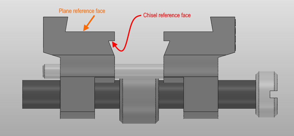
Some honing guides (for example the Veritas Mk2 one) reference off the same edge as the edge that is used to measure the protrusion. This means that the tool thickness has no effect on the bevel angle. Other guides (for example the Eclipse one) can use a different edge. To explain this better, this diagram shows the two reference faces that are used on the Eclipse honing guide:
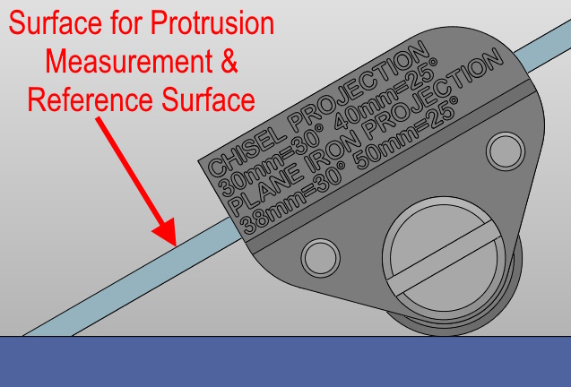
When honing chisels or other tools in the chisel jaws, the protrusion is measured relative to the reference face, so tool thickness has no effect:
However, when honing plane irons (or very wide chisels) or other tools in the plane iron jaws, the protrusion is measured on the unbevelled face of the blade while the reference face is the bevelled face:
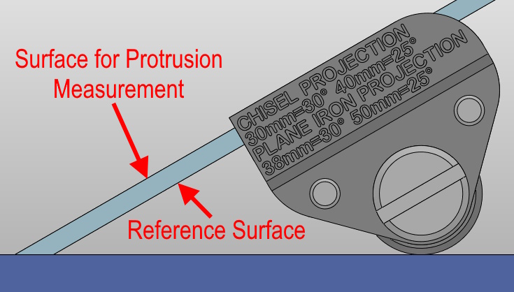
In the latter case, the thickness of the tool will have a (small) effect on the angle that you get for any given protrusion. This calculator takes that effect into account.
Offsets
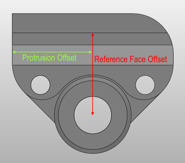
The reference face offset in the table above is the distance from the centre of the wheel to the face of the jig against which the tool is clamped. The protrusion offset is slightly more complicated to describe. If you draw a line from the centre of the wheel to the face of the jig against which the tool is clamped and ensure that line is perpendicular to the face, it is the distance from the point where that line meets the clamp face to the edge of the jig from which you measure the protrusion. Both of these dimensions are shown graphically in the diagram below (for the Eclipse guide and the plane iron reference face):
Background
This calculator uses the following equations:
Key
\(\qquad r\) is the radius of the wheel (half the wheel diameter).
\(\qquad d\) is the distance from the centre of the wheel to the top surface of the tool.
\(\qquad t\) is the tool thickness.
\(\qquad s\) is the reference face offset.
\(\qquad w\) is the protrusion offset.
\(\qquad p\) is the tool offset.
\(\qquad \theta\) is the bevel angle.
Calculations
Calculating top surface distance to the centre of the wheel:
This is quite simple when using the chisel jaws of the Eclipse guide (or for any other honing guide that references the top surface of the tool, like the Veritas Mk2 guide): $$ d = s $$ For guides that reference the lower face of the tool (like the plane iron jaws of the Eclipse honing guide), it becomes: $$ d = s + t $$
Calculating protrusion from bevel angle:
This can be seen diagrammatically in the following figure:
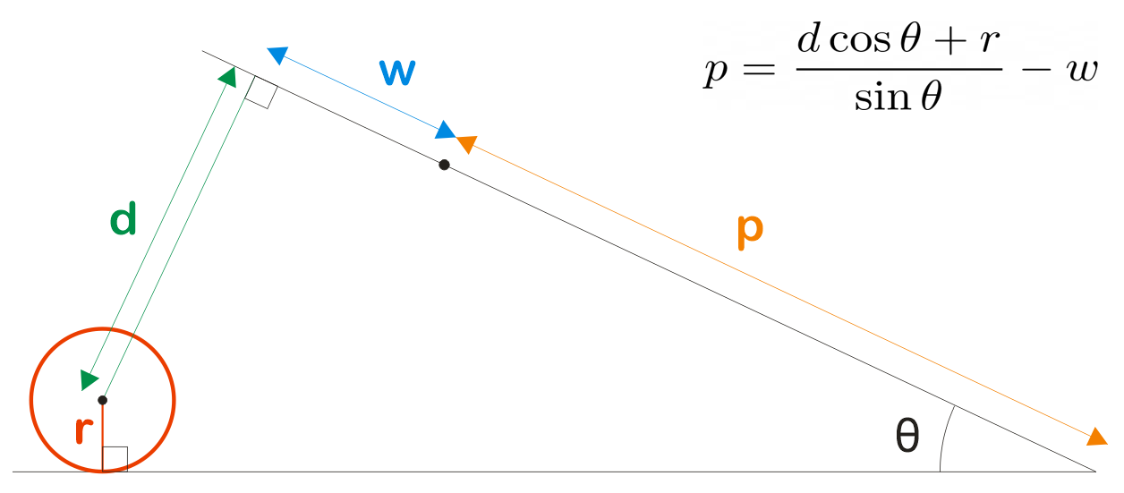
As shown in the diagram, the equation is simply:
$$ p = \frac{d \cos\theta + r}{\sin\theta} - w $$
Calculating bevel angle from protrusion:
To calculate bevel angle from protrusion uses a slightly more complex equation:
First we let \(l\) be the total protrusion including offset: $$ l = w + p $$ Then, $$ \theta = \cos^{-1}\left(\frac{\left(l \sqrt{d^2 + l^2 - r^2}\right) - r d}{d^2 + l^2} \right) $$
This website is free and ad-free, but costs me money to run. If you'd like to support this site, please consider making a small donation or sending me a message to let me know what you liked or found useful.
