Process
Page 4 of 5
Posted 17th October 2025
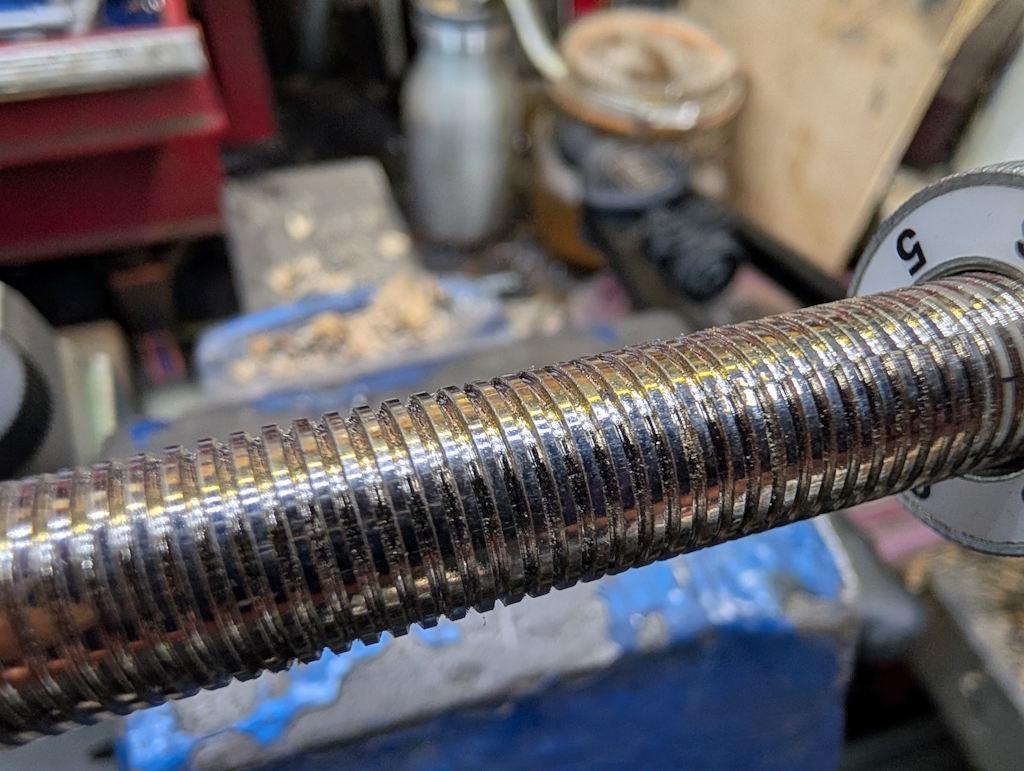
I thought it would be interesting to try to make a new "universal support" for the Tormek tools. The thread on the universal support is a bit of an unusual one:
It's (a tiny bit under) 12 mm diameter and it's a 1.5 mm pitch thread with what looks like a 60° thread shape. However, the thread hasn't been fully formed so it has large flats on the top. The reason for that is so that the clamp screw (which bears directly on the thread) won't damage the thread form (as it would if the threads were fully formed with narrow "lands" at the outer diameter).
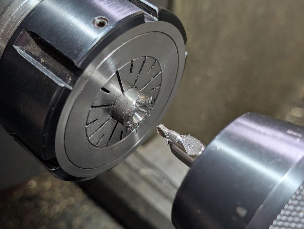
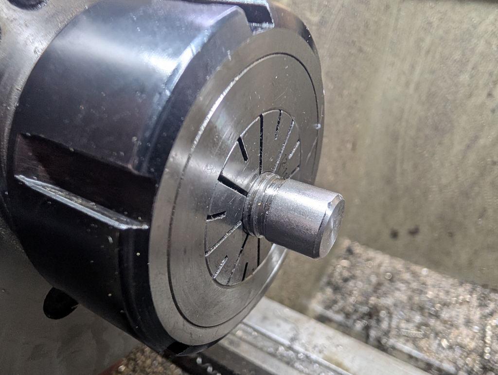
To make my own universal support, I need to reproduce that thread. I bought a metre length of 12 mm diameter 303 stainless steel and, after chopping a bit off, I put it in the collet chuck (I used a collet chuck here as I knew I'd need it later), faced and chamfered the end and then used a centre drill to form a centre hole in the end of the bar:
I rarely use centre drills as the thing I do most often that might involve them is starting drilled holes. Spot drills are much better for that purpose, so the centre drills only come out for their originally intended purpose.
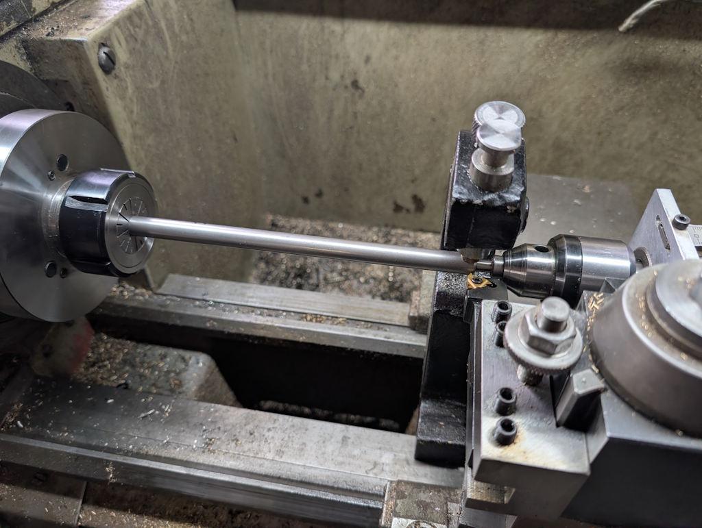
Another rarely used tool is a travelling steady. This is a fairly long thread, so I thought it seemed a good idea to take the time to set it up:
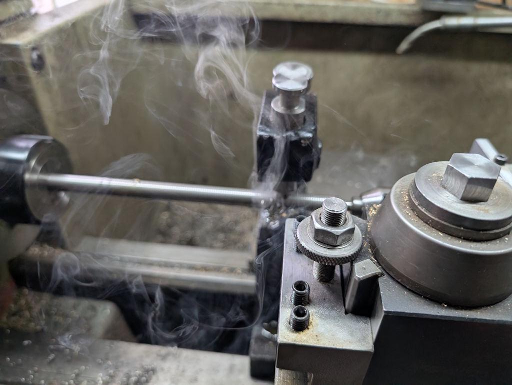
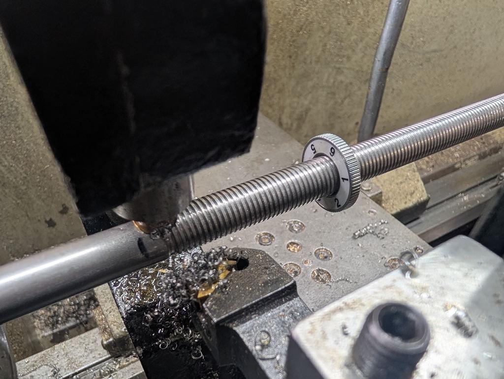
As I said earlier, the thread is a nice & civilised 1.5 mm pitch (the benefit of the Tormek being made in Sweden rather than the USA!). That made it fairly straightforward to keep taking long passes and being able to disengage the half-nuts at the end of each pass. I used lots of cutting oil (partly for cutting but also to keep the travelling steady lubricated). I tried to take an "action shot" during a cutting pass but apparently I got the camera focus wrong, sorry:
As it started to look vaguely right, I started taking light passes and checking with the Tormek nut after every pass. In not too long at all, the nut was running up and down the thread nicely:
After sawing off the excess in the bandsaw and then reversing the part in the collet chuck, I could tidy up and chamfer the end:
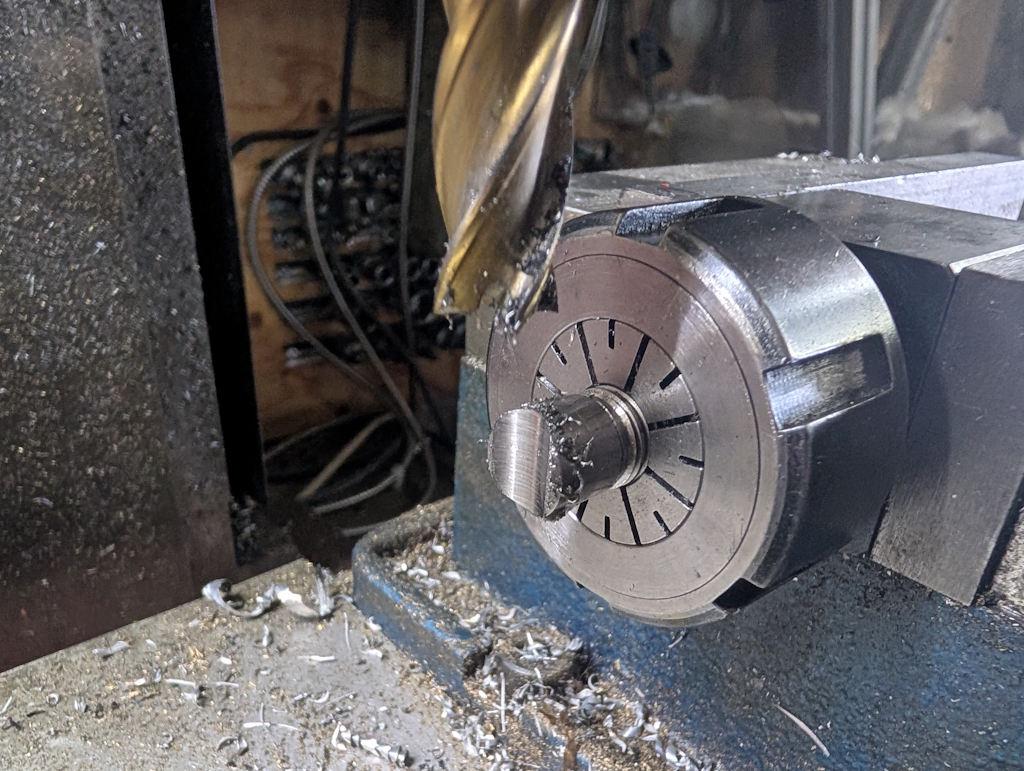
I then got rid of most of that tidied up face (but kept the chamfer) by putting it in a collet chuck in the milling machine vice and plunging a 12 mm end mill across the face (in a few passes):
"Off camera" (as the youtubers like to say) I also made another (unthreaded) bar with the curved notch (for the other of the two support bars) and tidied up and drilled/tapped M6 the ends of the bar that will form the rest itself.
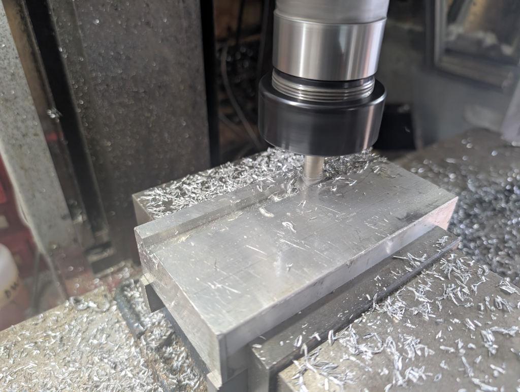
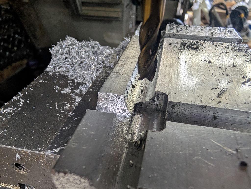
After digging around in my random aluminium bits drawer, I found this lump and used a 12 mm ball-end end mill to cut grooves in it:
I'm sure a square-ended end mill would have been fine here, but I had the ball-end one and I figured would be a closer fit and would help wick the welding heat away a bit better.
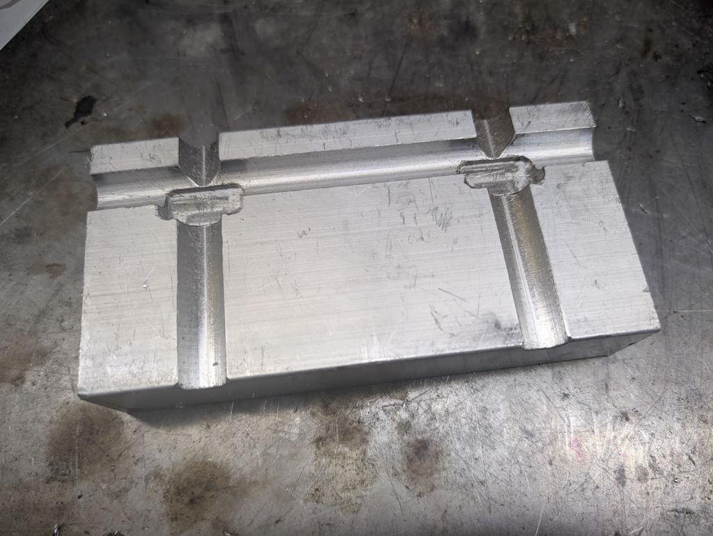
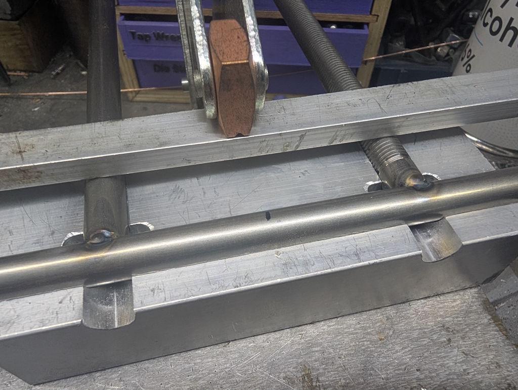
Speaking of welding, I also used a smaller (8 mm) centre-cutting end mill to make a bit of a pocket around the weld area to allow me to flip the part over after the initial tacks:
The finished jig, in need of a thorough clean before use:
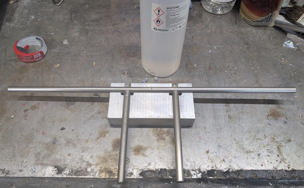
Everything (all three bars and the jig) got a thorough clean with acetone and then everything could be assembled ready for welding:
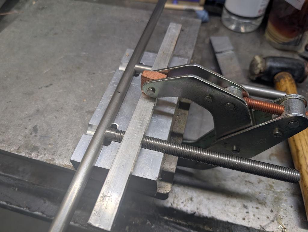
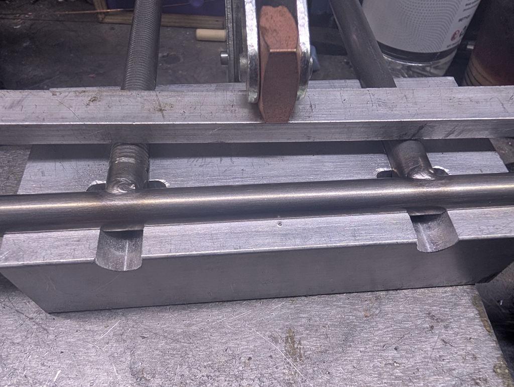
I'd been planning to use two or even three clamps to hold the parts in the jig, but in the end a single one did the job fine as the curved ends of the two clamped pieces had the effect of clamping the long bar in place quite rigidly:
I tack-welded the first side:
Then flipped it over and welded across the second side:
I then flipped it back again and welded across the first side, but didn't take a picture as it would have looked the same as the above.
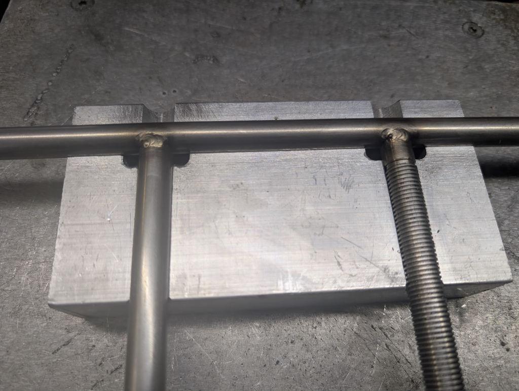
I must apologise at this point as the photos have been getting worse and worse throughout this post. I think I have a (bad) habit of touching the phone camera lens with my fingers, which were quite filthy and hence the pictures were getting fuzzier and fuzzier.
Anyway, after finishing the welding and letting everything cool down, I was really happy to see that the part fitted snugly back into the jig, implying I hadn't suffered from too much distortion during welding:
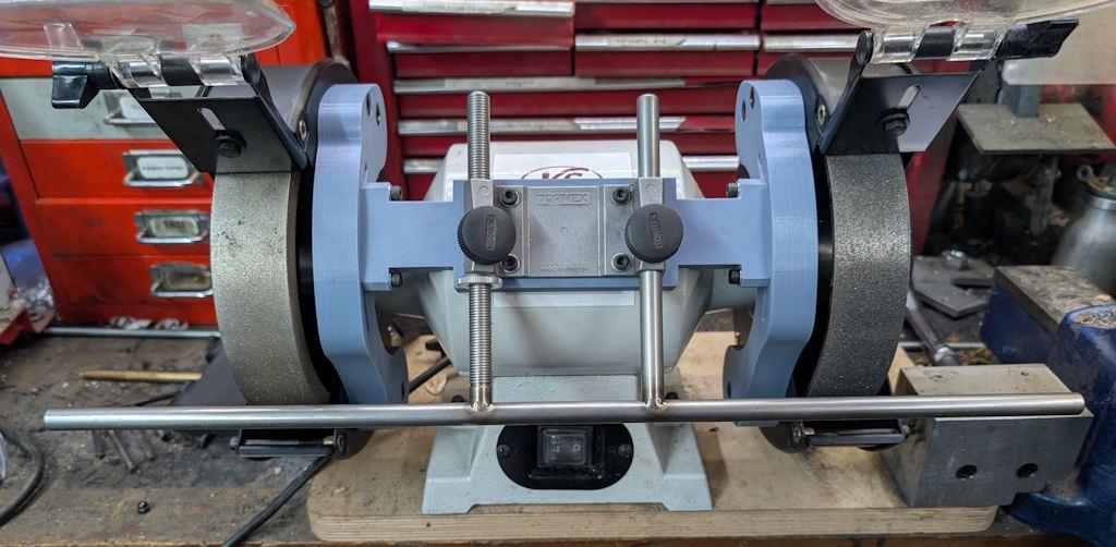
I could also try fitting it to the bench grinder and (after cleaning the camera lens!) get a photo of it in situ:
As the two wheels are exactly the same diameter (and, being CBN wheels, will stay the same diameter), I can set up a jig on the coarse wheel, roughly grind a tool to shape and then switch straight over to the finer wheel without having to move the support arm. That should save a bit of hassle, which is nice.
Page 4 of 5
This website is free and ad-free, but costs me money to run. If you'd like to support this site, please consider making a small donation or sending me a message to let me know what you liked or found useful.

 Return to main project page