Slow-Speed Grinder
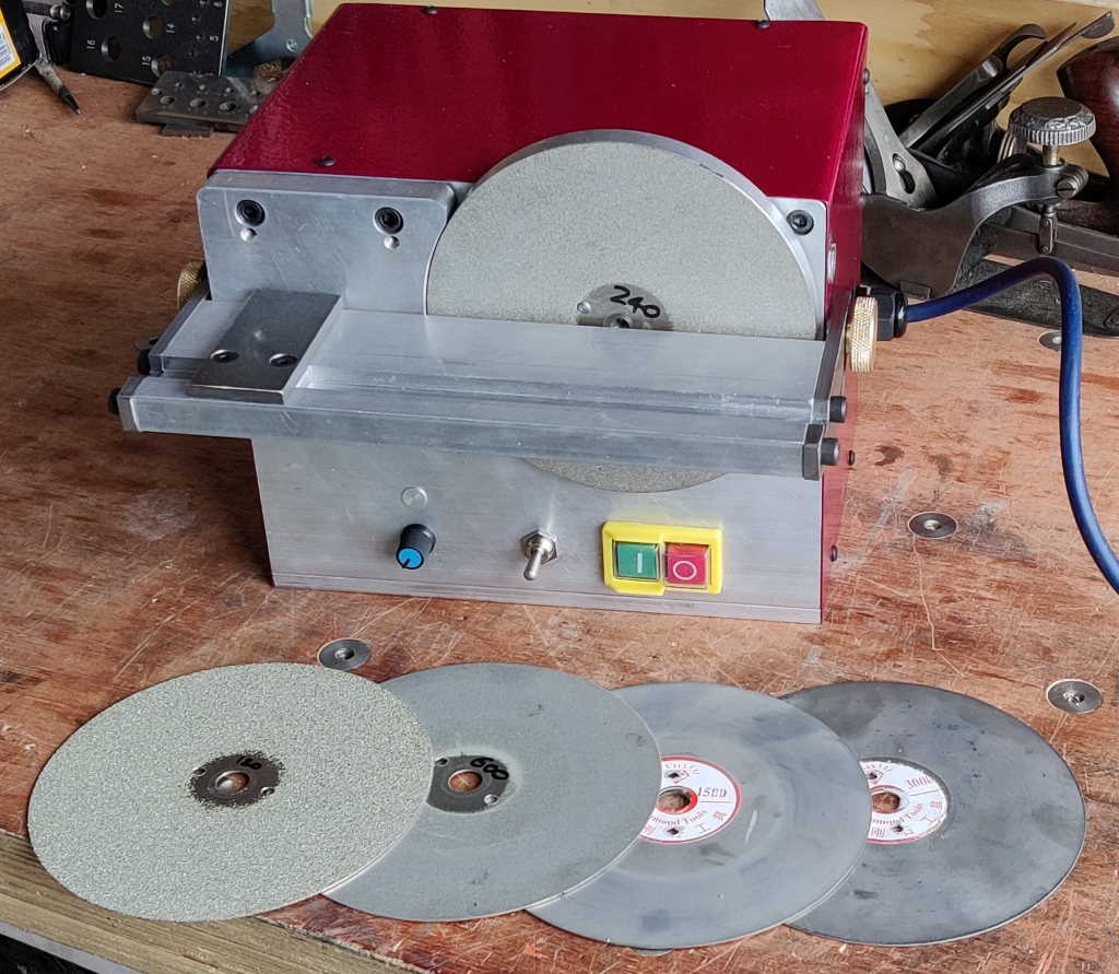
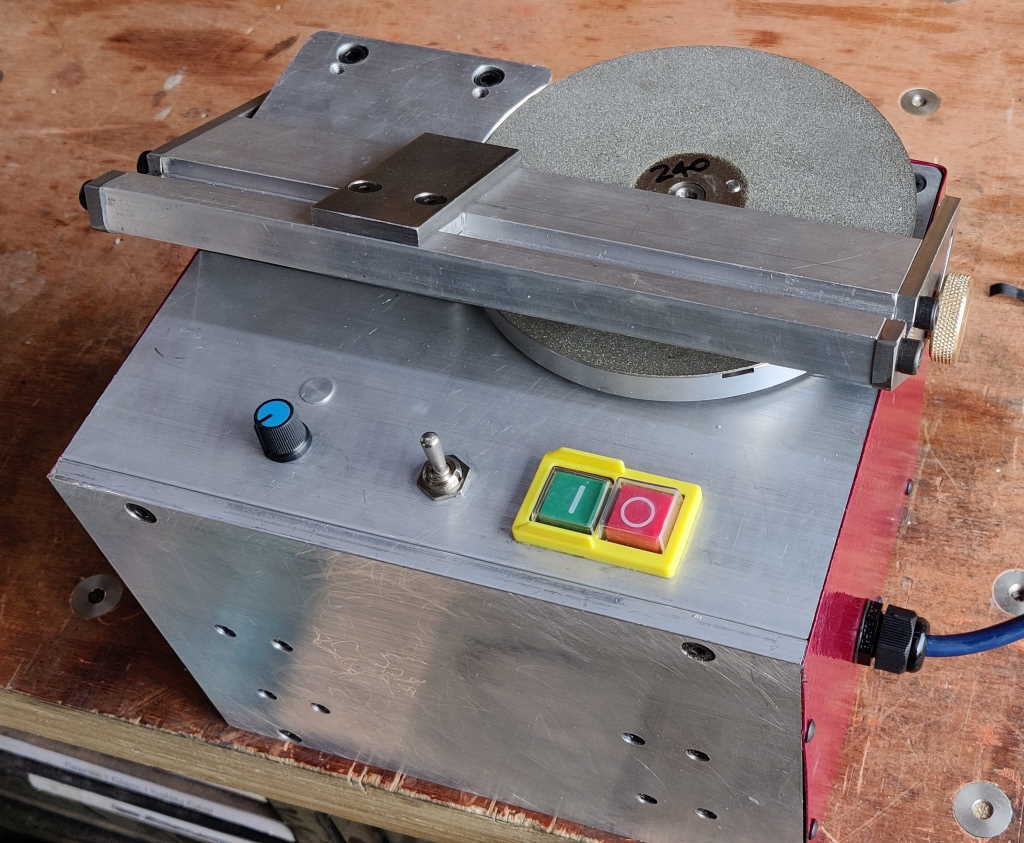
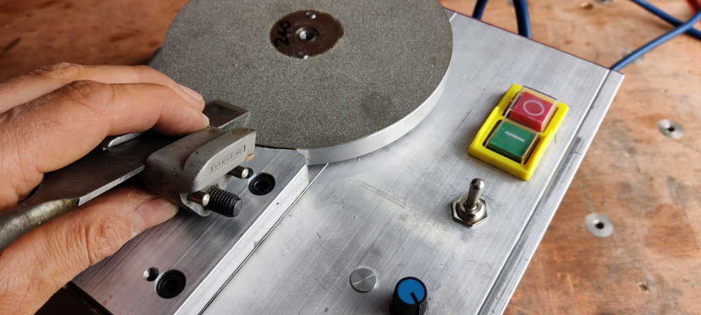
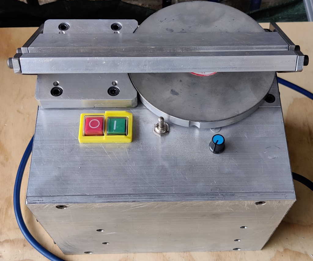
This is my home-made slow-speed grinder. It's based on an idea from Stefan Gotteswinter, although everything in my version was designed from scratch. It uses 150 mm diameter diamond grinding discs, which are cheap (the ones I bought were about £5 each) and have the advantage (compared to conventional grinding wheels) of being flat so surfaces prepared on the grinding disc can then be easily honed on a whetstone or waterstone. The discs are available in a range of grits from 80 to 3000. In practice I mostly use the 240 grit disc to make sure that chisels and plane blade cutting edges are square to the sides; I then put a secondary bevel on the blade with a fine grit waterstone. The only times I use the finer grits are when flattening the backs of chisels. The grinder is powered by a variable speed controller driving a brushed DC motor and runs at speeds up to 400 rpm in either direction (clockwise or anticlockwise).
The aim of the grinder is to allow a method of reshaping second-hand (or badly ground new) tools prior to putting them on a waterstone. Before I built this grinder, I tended to use a piece of coarse grit (e.g. 120 grit) wet-and-dry paper on a flat surface to get the cutting edge square to the end and I would then move onto the other stones. For some (particularly wide) chisels, this process took a very long time and was rather tedious. Trying to use a conventional bench grinder required a huge amount of care & attention to ensure that the blade didn't get too hot. As my slow-speed grinder has a flat surface and turns much more slowly than a bench grinder, the process is much easier and more accurate.
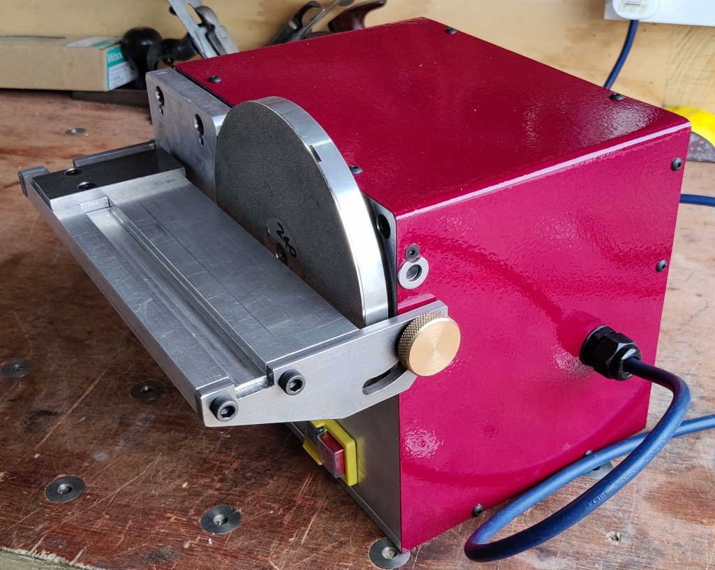
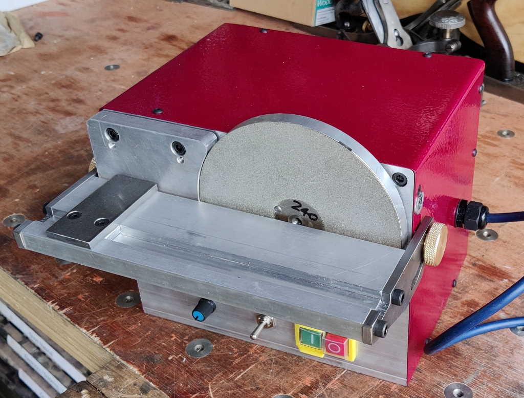
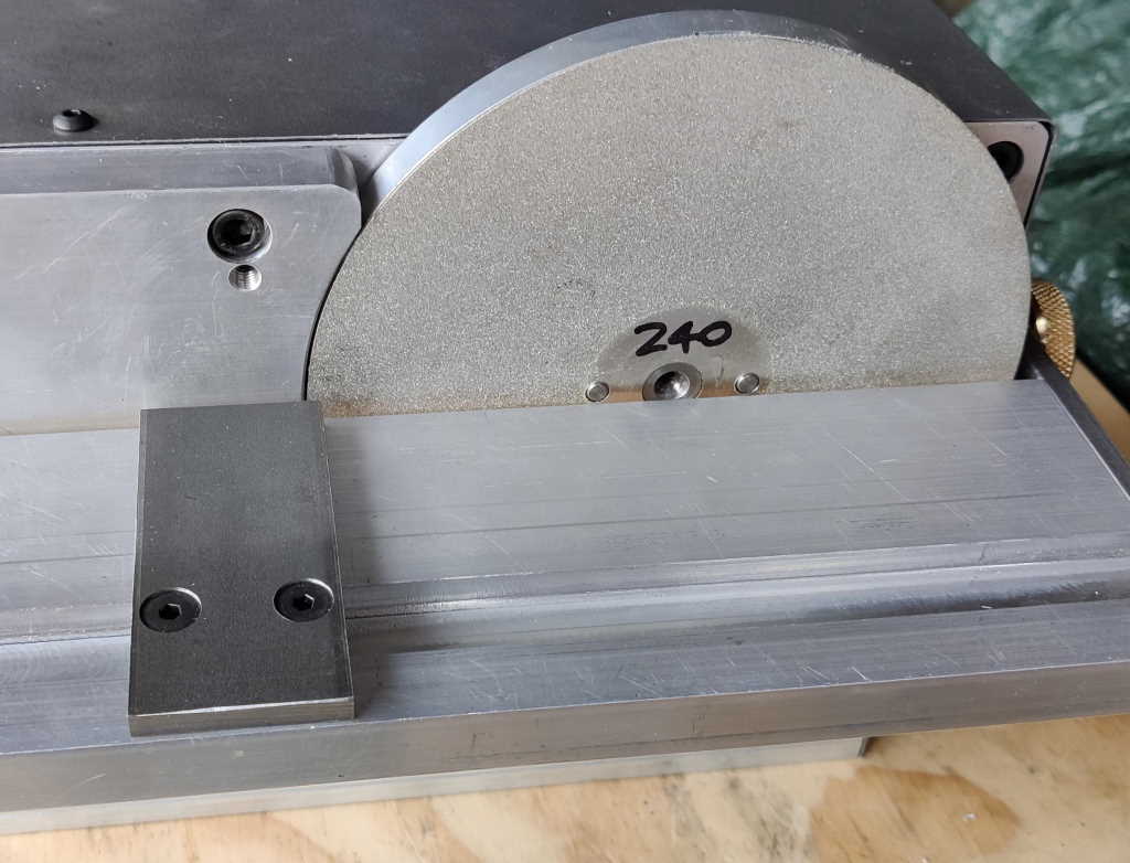
These photos show a couple of other views of the grinder with the table fitted, along with a 240 grit diamond disc. The slot in the table is 15 mm wide and just over 6 mm deep. This size was chosen as I had a reasonable length of 6 mm × 15 mm steel stock that could act as a runner to go in the slot and allow fences to slide parallel to the face of the disc. The table is designed to have enough clearance from the disc that the disc can be changed (typically for a finer grit) without moving the table so the angle can be maintained as you work through the grits.
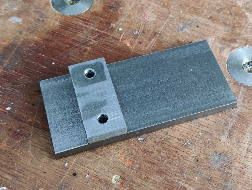
These photos show the fence. It is simply made of a piece of 6 mm × 15 mm × 35 mm mild steel (EN3B) attached to a piece of 6 mm × 35 mm × 80 mm mild steel (also EN3B). It can slide freely to the left and right along the fence but ensures that a tool placed against the side of the fence will be perpendicular to the disc.
The grinder can also be positioned with the disc at the top. In practice this is how I use it most as it works better in this orientation when grinding a fairly steep angle as you would with a chisel or plane blade.
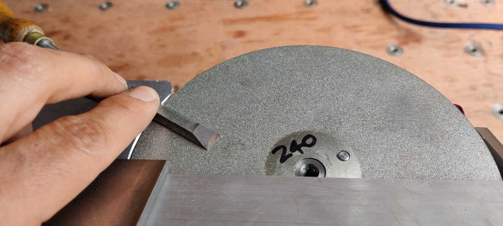
These photos show one way in which the grinder can be used to shape (or sharpen) a chisel. The left-hand photo shows the chisel with the back being ground flat (in this case using the reference surface - described later - for convenience, although this is not necessary if the speed is kept low).
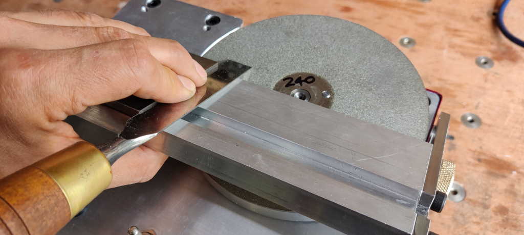
The reference surface (the aluminium plate with the curved edge next to the disc) can be adjusted (using four M6 grub screws and four M6 cap screws) such that it is parallel and level with the disc. This is fairly time-consuming to set up, but once done it doesn't need to be adjusted again. With the reference surface level and parallel, another way that the grinder can be used is with the tool to be sharpened held in a honing guide, as shown in the photo above. In practice, I use this more often than the table and fence as I can take the tool and honing guide straight from the grinder to a fine grit waterstone and get a very sharp edge very quickly.
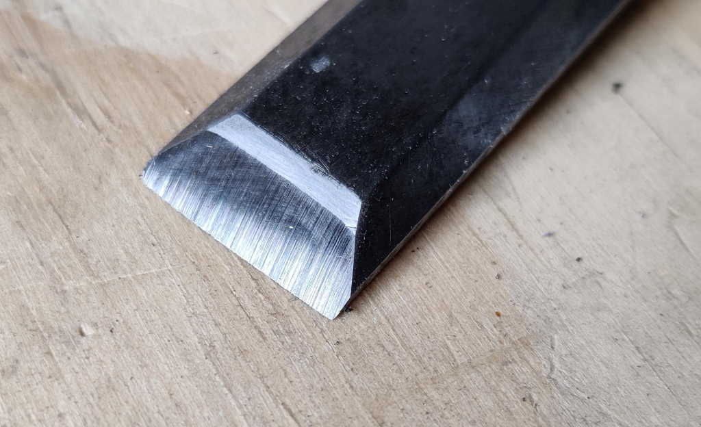
This photo shows a chisel (which had a substantially curved edge on it when I got it second-hand) after being ground (using the table and fence in this case) on a 240 grit disc. You can see that the edge is now square with the sides and it is ready for a secondary bevel to be added on a waterstone. The process of straightening up the edge took less than a minute on the slow-speed grinder and the edge was still cool to the touch after grinding.
This photo (taken before I had decided to invert the switchgear panel so that the switches were further away from the disc) shows the table mounted in an alternative position. This position can be used when grinding tools that are wider than about 50 mm (the distance between the edge of the diamond disc and the inner uncoated area of the disc). With the table in this position the maximum tool width is well over 100 mm, although it has to be used with care as one side of the disc is moving upwards and hence trying to pull the tool away from the table. When using the grinder in this position I keep the speed low to prevent the tool being lifted.
Construction
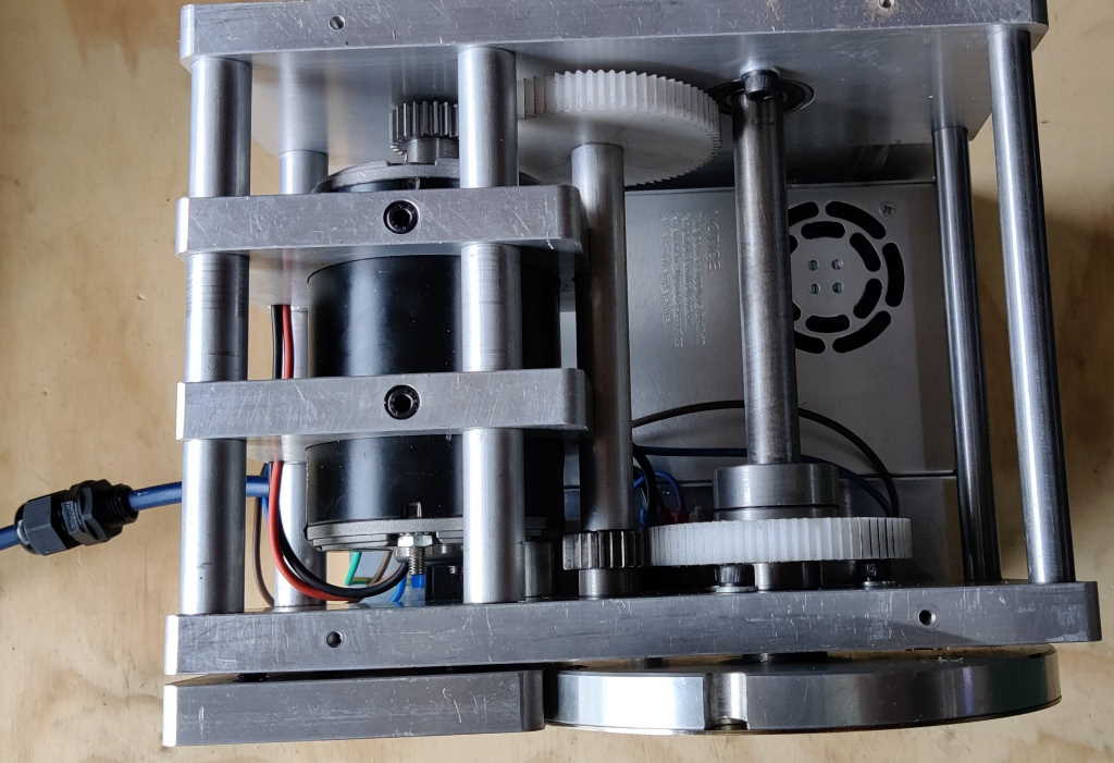
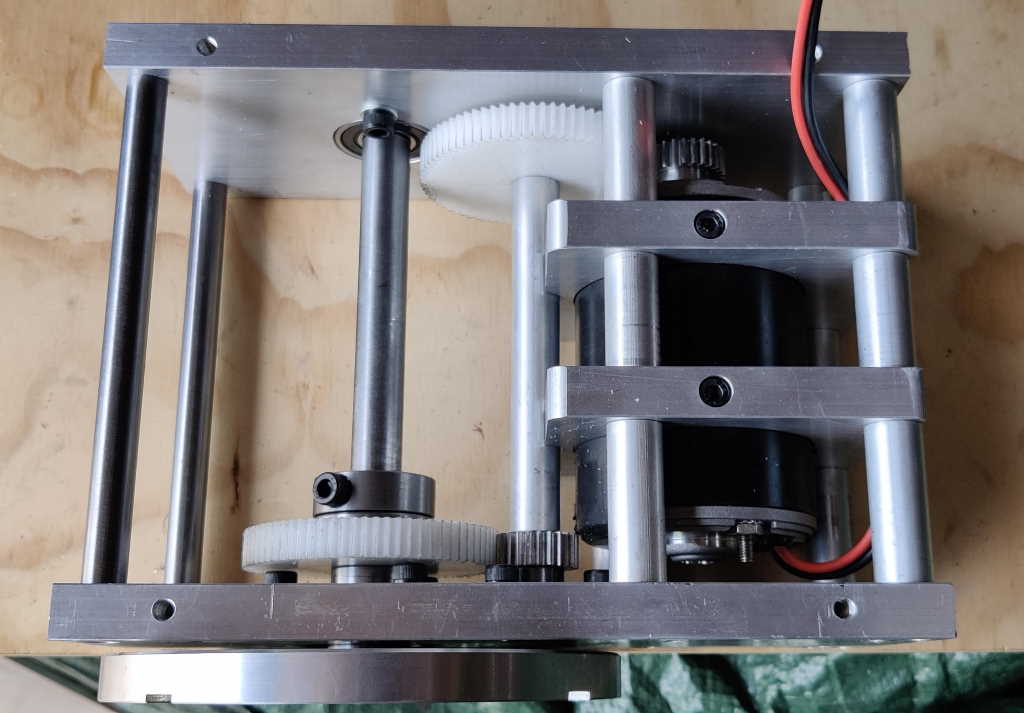
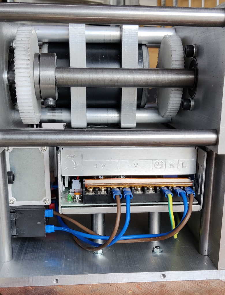
The photos above (like all photos on this site, you can click on them for a bigger view) show a couple of views into the drive assembly housing. The motor is a 24 V, 250 W brushed DC motor that has a no-load speed of 3600 rpm. A 25 tooth module 1 gear is attached to the output shaft with a grub screw (bearing on a flat filed on the shaft and held in place with thread locking compound). This drives a 75 tooth gear on the middle shaft (with a 3 mm key joining gear to shaft). The other end of the middle shaft has another 25 tooth gear (again with a 3 mm key). This drives another 75 tooth gear on the output shaft. The middle shaft and output shaft run in bearings in the outer two plates; the motor shaft relies on the bearings in the motor.
The electronics assembly at the bottom is fairly tight, particularly at the top of the assembly. There is a 20 A, 24 V power supply occupying most of the space and then a cheap 20 A motor speed controller mounted to the side. The power supply is raised on pillars to give space for the wires on the back of the two switches (a no-volt release switch on the power supply input and a direction switch on the motor controller's output) and the potentiometer that controls the speed.
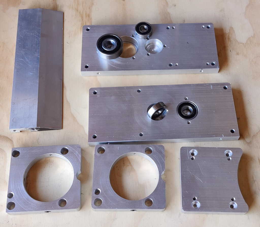
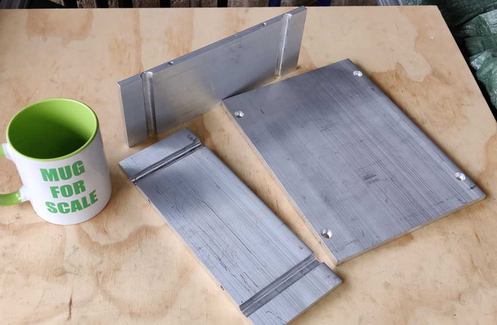
These photos show the aluminium components that make up the drive assembly. Manufacture of these was relatively simple with a milling machine with a digital read-out, although it took quite a long time with the large number of large holes, which were all bored with a boring head.
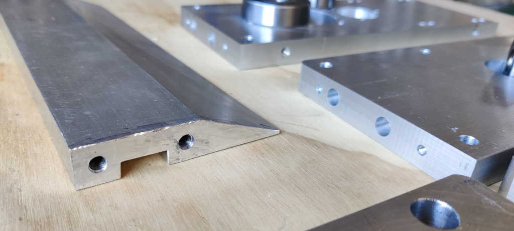
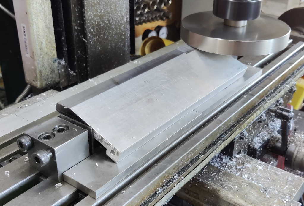
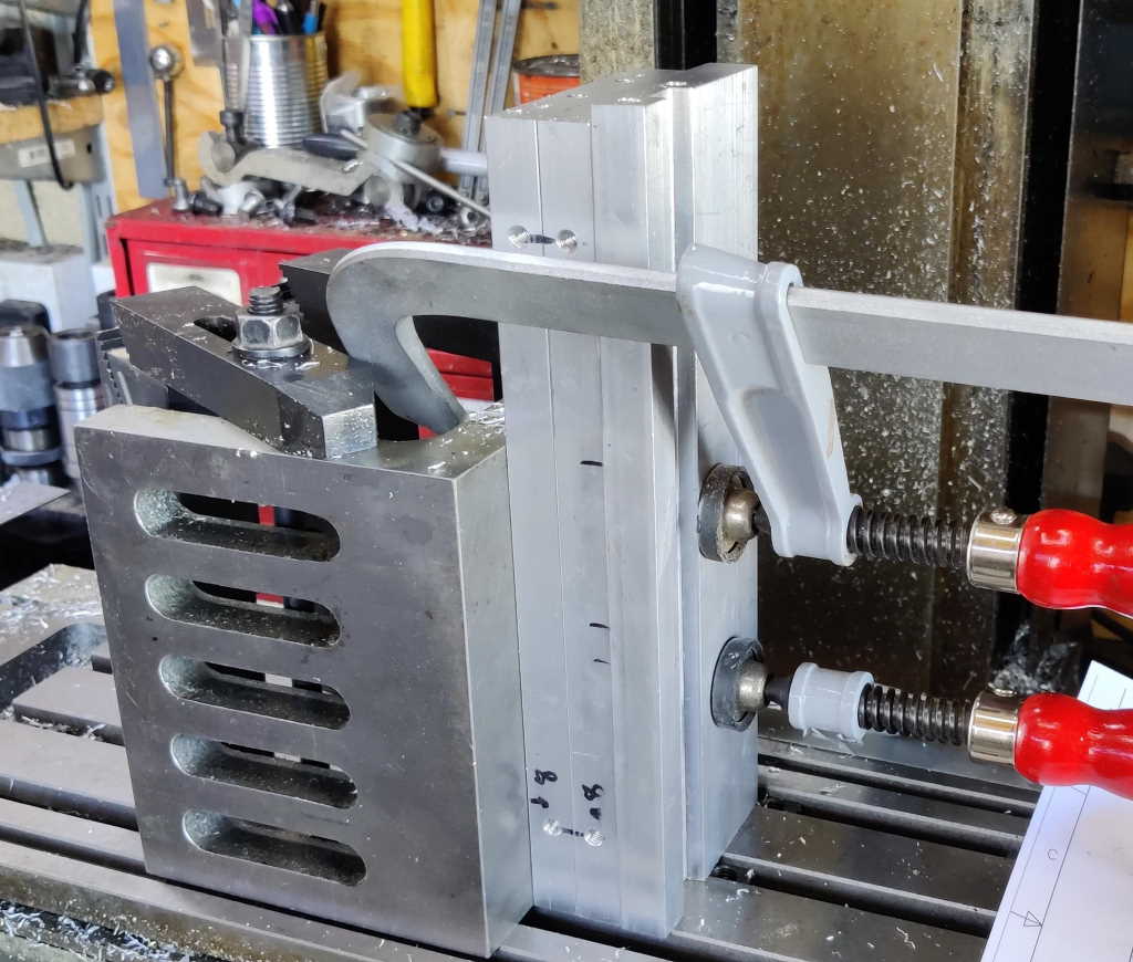
The most complicated manufacturing jobs for the aluminium parts were making the table and drilling the holes in the ends of the long parts. Machining the steep taper (which is required to allow chisels to be sharpened with bevel angles down to 20°) on the back of the table was done by holding the table between two high-profile clamps and using my flywheel fly cutter to skim the angled surface. I did this after cutting the other features so that the rest of the machining could be done on a rectangular prism for ease of work-holding. Machining the details on the ends of the bars was simple enough in principle, but I had to pick through my selection of collet chucks to find the shortest one as the clearance with the milling machine head at the top setting was insufficient with almost all the chucks I tried!
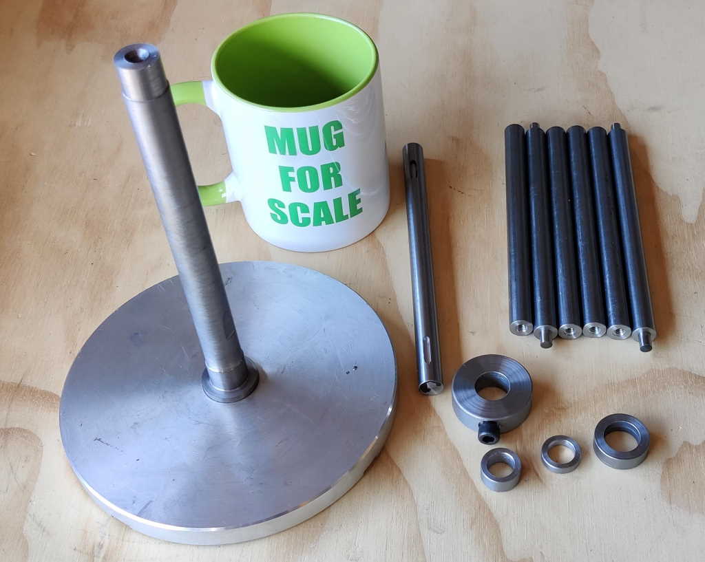
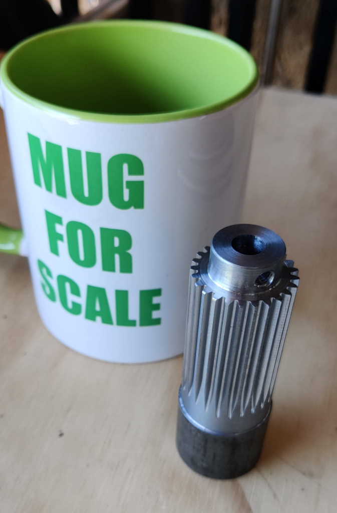
These two photos show the various turned parts that make up the drive assembly. The six pillars in the top-right of the photos separate the two plates that hold the bearings. Four of these pillars are held in place with M6 cap-screws; the middle two have dowel pins for more accurate location as they control the position of the motor relative to the middle shaft. The various washers are used to hold the gears at the right spacing from the bearings.
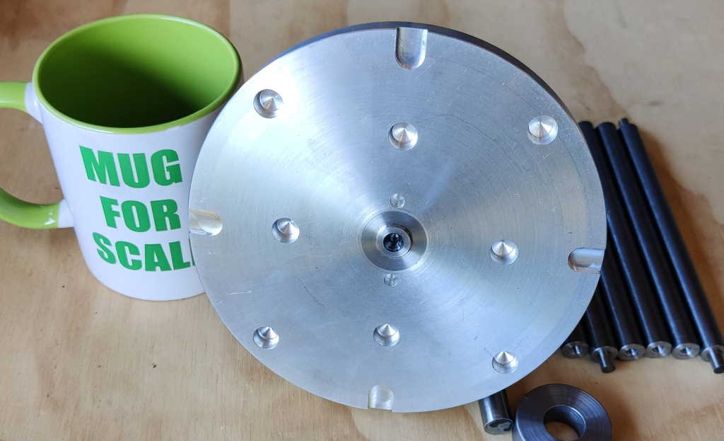
The large disc was made from a piece of aluminium I found in a skip. It was faced on one side and a 24 mm hole bored through the middle. I then made the steel shaft that goes through the middle. The section that goes into the aluminium faceplate is about 20 μm larger than the bored hole. To join the two parts together, the aluminium faceplate was placed into our kitchen oven at maximum temperature (about 240°C) and the thermal expansion allowed the steel shaft to be inserted. Once the two parts were joined, the faceplate's outer surface could be faced and it could be turned down to the final diameter. It was then mounted on the milling machine and the various holes drilled. All the turning on the steel shaft (before and after attachment to the aluminium faceplate) was between centres.
The central boss in the steel part of the faceplate is 12.7 mm (1/2") diameter as that is the size of the bore in the diamond discs I bought. The two holes either side are 5 mm diameter and spaced 32 mm apart. These line up with the uncoated part of the diamond disc and I drilled corresponding 5 mm holes in each of the diamond discs. Small steel pins are glued into each of the two faceplate holes (with Loctite 603) and these act as drive dogs to ensure the discs turn with the faceplate. The other holes in the faceplate hold 10 mm diameter, 3 mm thick neodymium magnets to hold the diamond disc to the faceplate. The slots around the outside were intended to be used with a screwdriver or similar to help with levering the discs off. As you can see if you look closely at the first photo in the "Construction" section, I later added a cut-out in the edge of the faceplate where two of these slots lie - that removes the need for a screwdriver and the disc can be pulled with a finger. The cut-out also helps with assembly as the disc covers the counterbored holes for two of the screws that hold the drive assembly together.
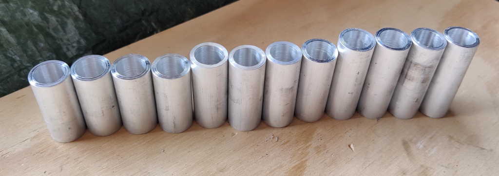
The pillars that surround the motor have some aluminium tubes slid over them. These hold the two motor brackets at the right distance from the edge and ensure that the motor can't move axially. The motor is held into its brackets with some M5 cap screws bearing on the motor's housing.
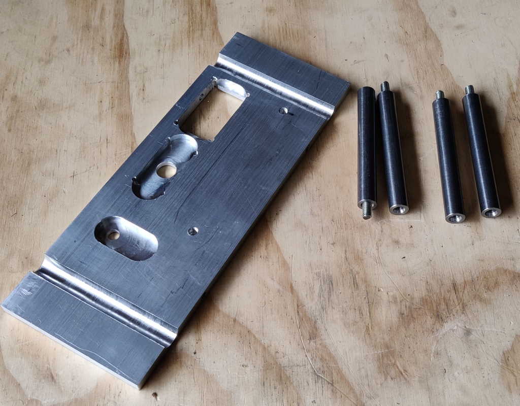
These two photos show some of the parts that form the electronics enclosure. The first photo was taken before machining the mounting features (for the power supply) in the base plate and also before machining out the holes for the switchgear in the side plate. The second photo shows the modifications made to the front plate to allow the switchgear to be fitted.
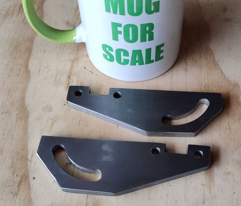
The brackets were fairly complicated to make due to the slotted arc. All of the machining was done with the parts clamped together on a rotary table mounted on the milling machine. I used five clamps to hold the parts in place and removed and replaced them one at a time as I worked my way around the edge of the fledgling parts.
The cover was made from some 0.8 mm mild steel sheet. I bent it using my sheet metal bender and then used some simple home-made transfer screws (made by filing down the ends of some grub screws) to work out the positions of the required holes. It was painted using one coat of Tractol light grey primer and two coats of Tractol RAL4004 (Claret Red) machinery enamel, applied with a paint roller.
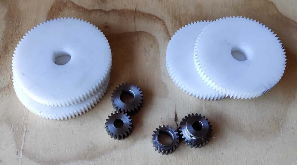
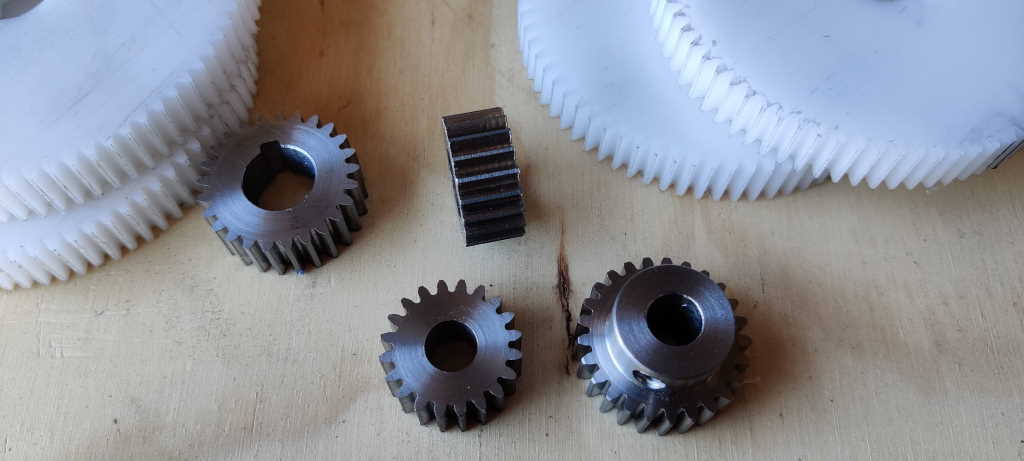
I made a few different gears as part of the manufacturing process as I was undecided about what speed to run the grinder at. The gears you can see in the pictures include 20 tooth gears, 25 tooth gears, 75 tooth gears and 80 tooth gears. These give the option of gear ratios of 16:1, 12:1 or 9:1 without changing the gear spacing. When I originally started the project I hadn't intended to include a variable speed drive so I wanted to be able to tweak the gear ratio for the best speed. The variable speed drive I bought meant that I didn't need to worry too much about getting it exactly right, so I went with the 9:1 ratio.
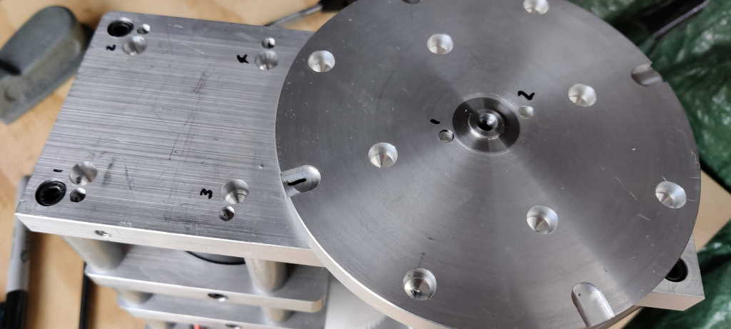
This photo shows the assembled drive assembly before the reference plate has been added and before the magnets and steel drive pins have been glued into the faceplate. You can see the four threaded holes into which the M6 cap screws in the reference plate go. Alongside these threaded holes are four 10 mm diameter holes (marked 1, 2, 3 & 4 in the photo). These holes lie directly underneath the grub screws that set the height of the reference plate. Short pieces of steel were glued into these holes (after machining each to be the right length for its hole so that it was flush with the top of the plate). The steel inserts give the grub screws something harder wearing (than aluminium) to push against.
This website is free and ad-free, but costs me money to run. If you'd like to support this site, please consider making a small donation or sending me a message to let me know what you liked or found useful.

