Portable Workbench Build Process
Page 23 of 67
Posted 18th March 2021
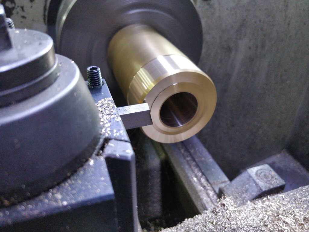
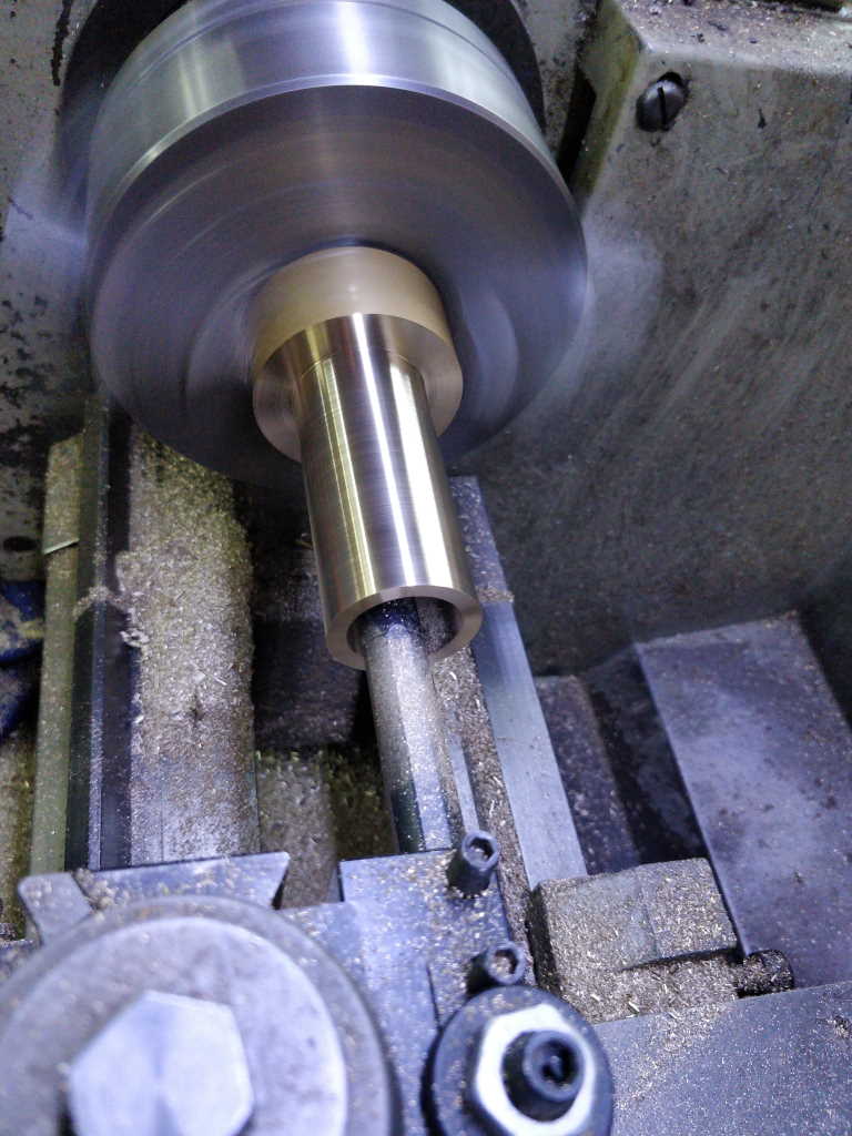
I then put my upside-down tool in the tool post, set the lathe to run backwards and faced off the end:
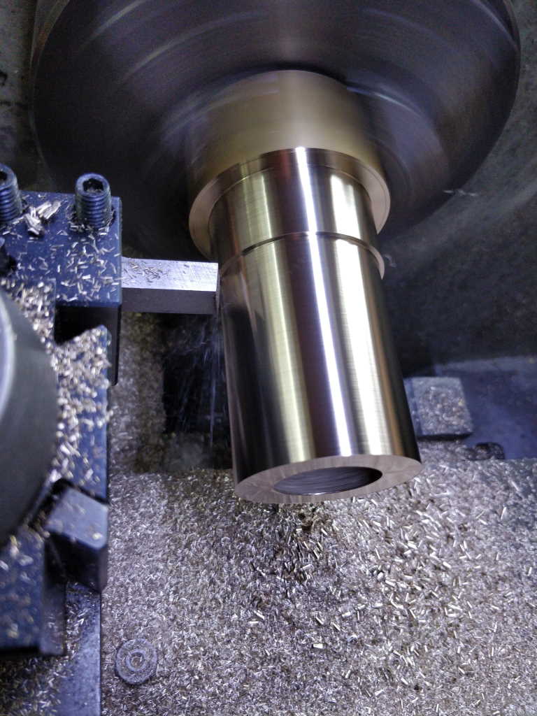
I then turned the outside diameter down to about 0.5 mm over the target diameter (40 mm).
Once that was done, I wandered off and did some tidying at the other end of the workshop for half an hour while the workpiece cooled down. It's probably not that critical for this application (it's not exactly a bearing fit or anything), but I wanted to give myself the best chance.
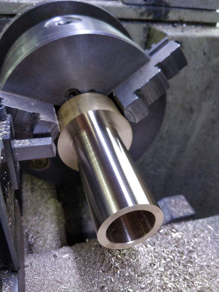
Once it was back down to room temperature (which didn't take that long as it hadn't actually got that hot), I took a final pass on the outside diameter and then faced the inside surface of the flange:
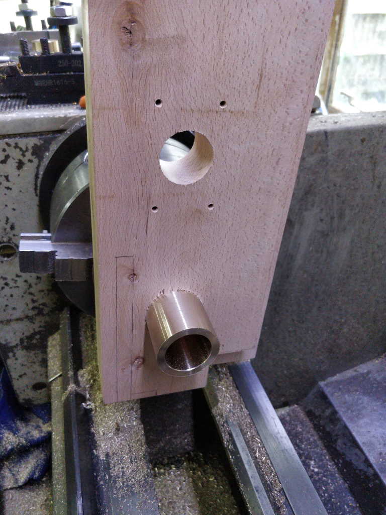
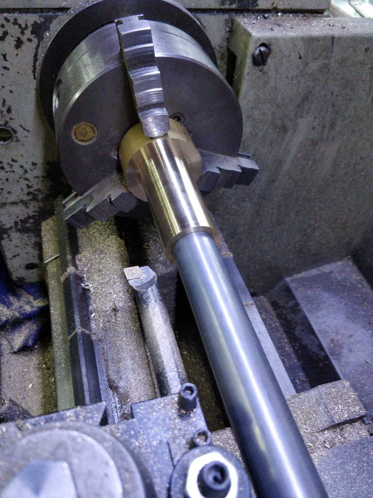
This seemed a good time for a test fit of the outside diameter in the fixed jaw:
The boring bar then went back onto the tool post and I took a lot of passes (with repeated "spring" passes at each setting of the cross-slide) to gradually sneak up on the final diameter.
As I got close, I used the steel tube as a reference, rather than relying on the bore gauge to measure the size.
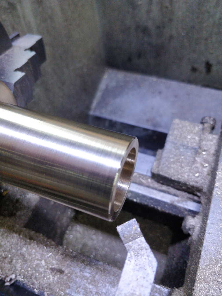
Finally, I chamfered the end to tidy it up a bit. I also chamfered the inside edge, but I just did that with a hand held deburring tool while spinning the chuck with my other hand.
Page 23 of 67
This website is free and ad-free, but costs me money to run. If you'd like to support this site, please consider making a small donation or sending me a message to let me know what you liked or found useful.

 Return to main project page