Portable Workbench Build Process
Page 4 of 67
Posted 8th March 2021
I started by cutting the beech into lengths of roughly double-plus-a-bit what was needed for each component. The "double" was because there's two of each component type, the plus a bit was to try to allow for the snipe of my thicknesser. I didn't quite get that right and there's a little evidence of snipe on the ends of the outside face of the moving jaws, but I'll probably just round those ends off and it'll disappear (it's only about 7 mm into the ends of the pieces).
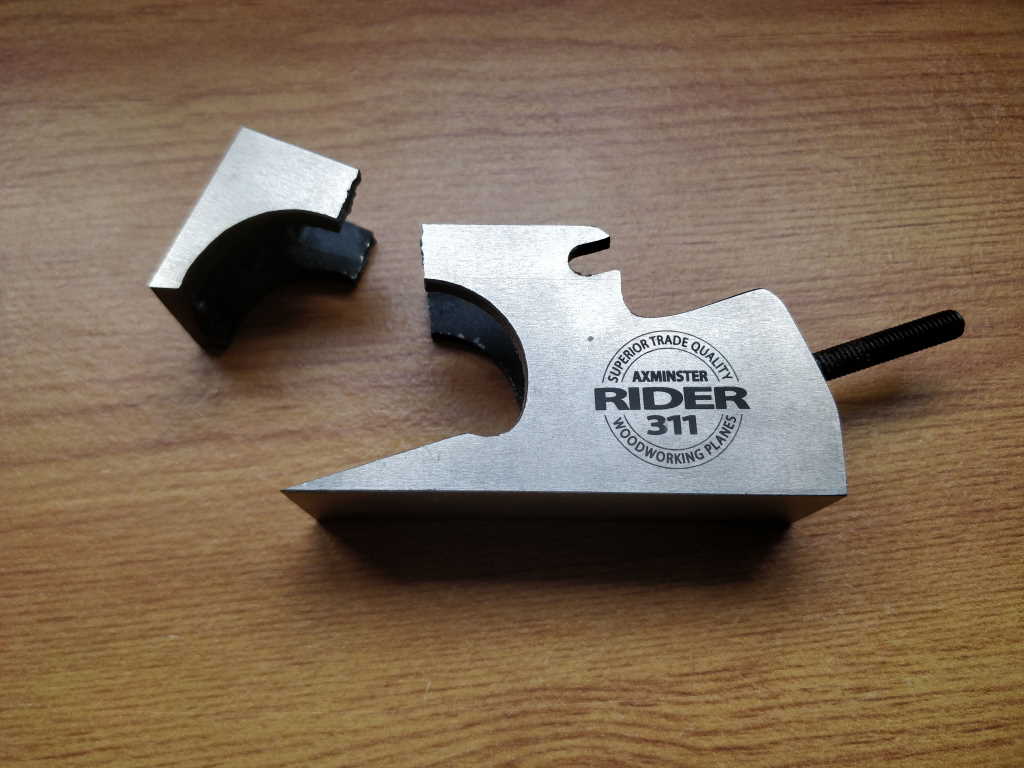
I then used the table saw to cut a rebate into the fixed jaws. I (deliberately) cut it a bit too shallow so that I could tweak it down to size with my shoulder plane. I then proceeded to drop my shoulder plane on the floor at the end of a stroke:
That made one or two rude words come out of my mouth…
Thankfully, I also have a Stanley #78, so I was able to use that to sort the rebate out while I wait for Axminster to tell me whether I can buy spare parts or if I'm in the market for a whole new plane. With hindsight, the #78 was the better tool for the job anyway, so I should have reached for that first!
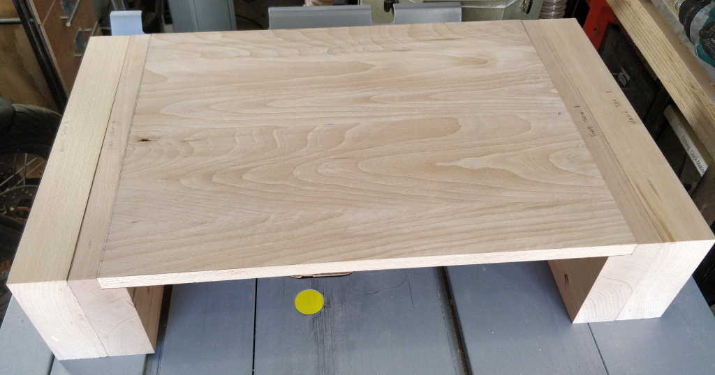
I then did a quick test fit of the jaws and table top:
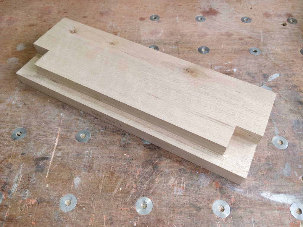
Next job was to cut the blind rebate (is that the right word?) for the rail to sit in. I did this by cutting diagonally with a dovetail saw and then sorting the rest out with a chisel:
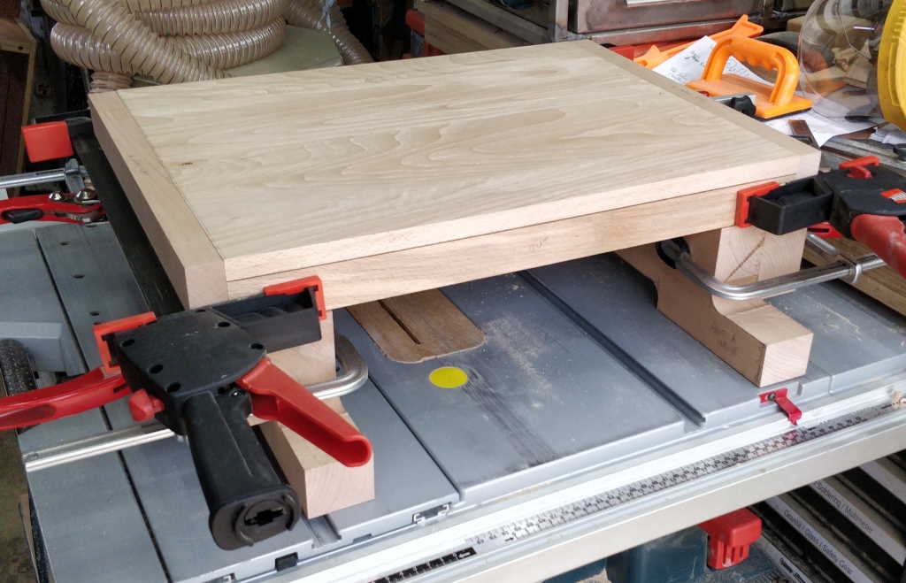
The legs were roughly shaped with a mixture of tools: 32 mm Forstner bit for the various radii, then hand saws, jigsaw & finally a saw rasp for a bit of finer shaping. I could then put it all sort-of-together to see how it would look (moving jaws removed for easier clamping in this photo):
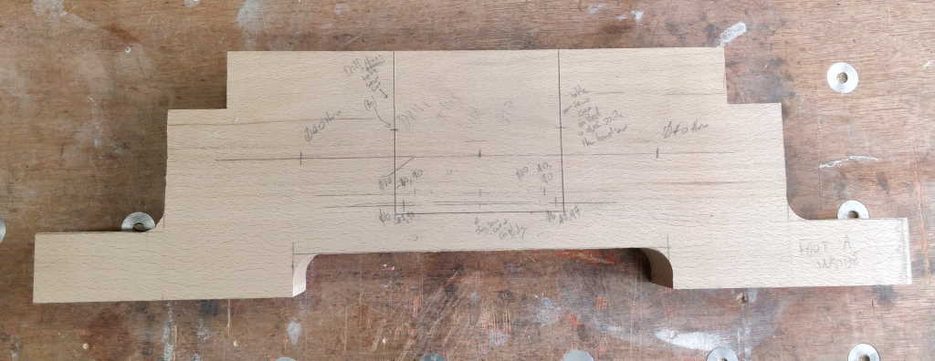
I knife-marked out the slots (in the feet) for the vice mechanisms in both feet and also marked all the hole locations in pencil. Here's the foot that sits at the end with the conventional vice (I didn't take a photo of the other foot in this state) with the central vice mechanism area marked out:
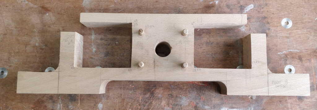
and here's what the other one looks like after drilling and then removing the wood in the area where the vice mechanisms will sit. Those slots were cut out with a hand saw for the accessible edges and a jigsaw for the inaccessible ones. I then used a chisel to tidy up the sawn edges.
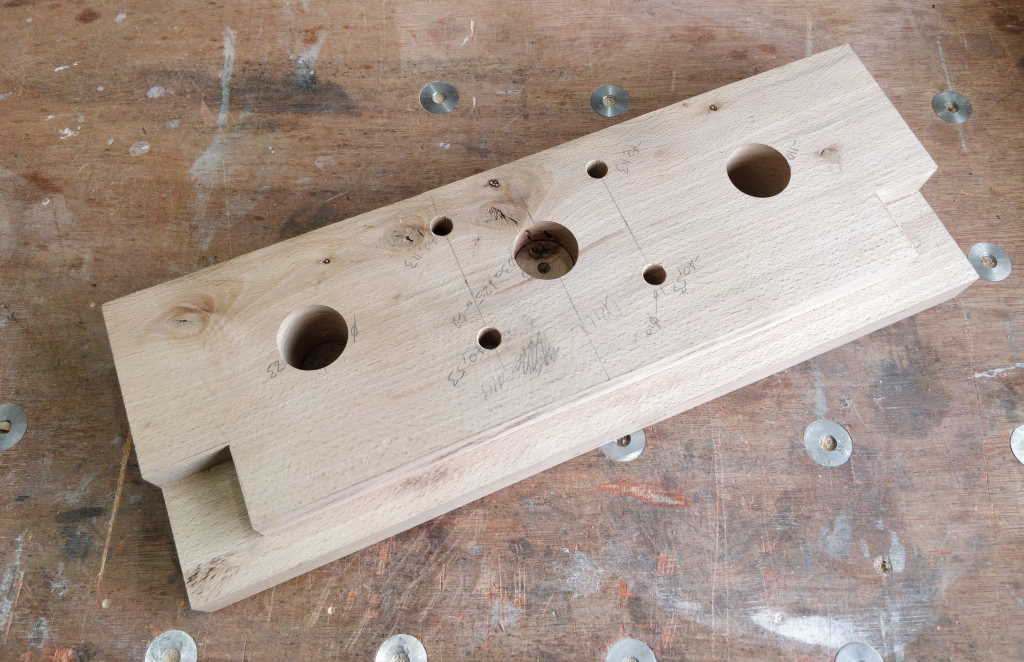
The way I've designed it, it's really important that the spacing of the three main holes is exactly the same on all four jaws (two fixed and two moving) and in some cases the feet as well. They also need to be perpendicular to the faces and a consistent distance from the top surface. The slide rails for the standard vice need to slide smoothly in the bushes (which will be mounted in holes in the fixed jaw and the foot at the standard vice end). They also need to slide over the threaded rod that forms part of the mechanism for the dual-screw vice. Any inaccuracies in the hole locations will mean the vice mechanism binds up.
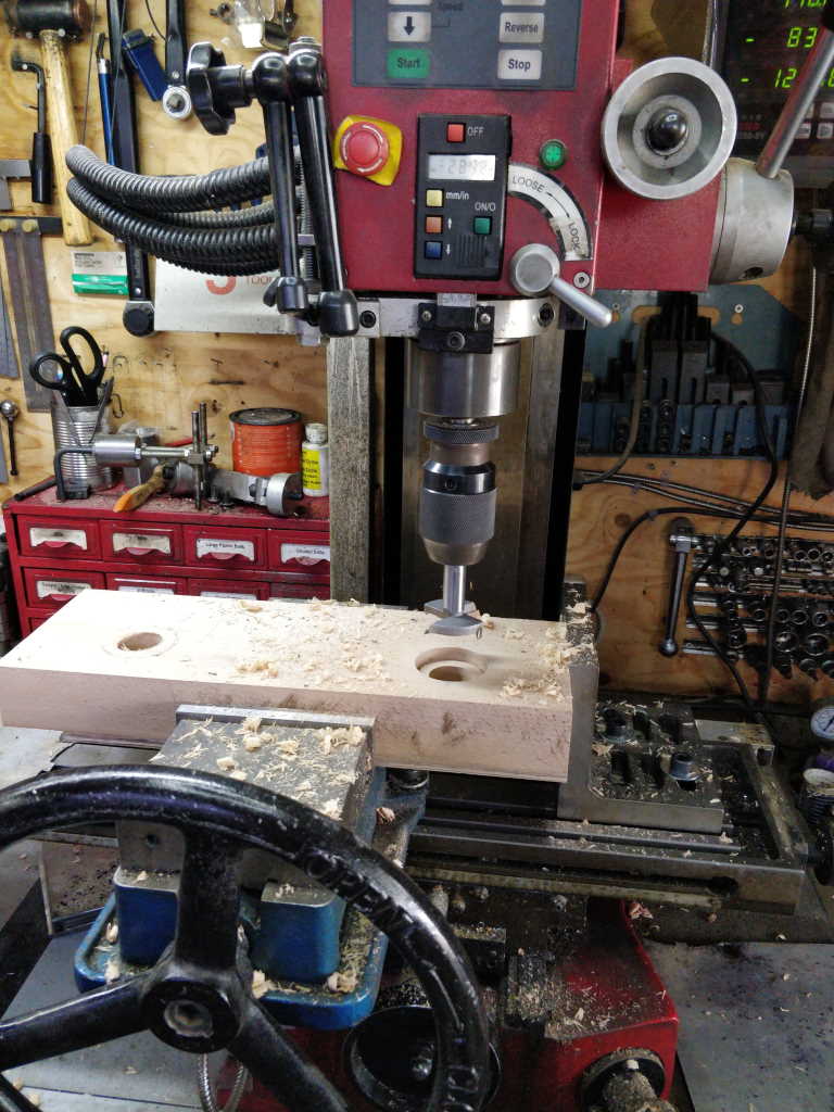
Fortunately, I have a milling machine with a digital read out…
The angle plate you can see on the right gives a consistent reference so that I don't have to re-zero the X-axis every time I place a new part in the vice. If there's a small offset in that axis it won't affect function: it'll just mean the edges don't quite match up. The jaws were all cut in the same setting, so there shouldn't even be an offset, but it's not the end of the world if there is: the important reference is the milling machine vice's fixed jaw, which references the top surface of each part.
Everything looks like it's in the right place so far…
That pretty much brings us up-to-date so far. More to follow.
Page 4 of 67
This website is free and ad-free, but costs me money to run. If you'd like to support this site, please consider making a small donation or sending me a message to let me know what you liked or found useful.

 Return to main project page