Sheet Metal Bender
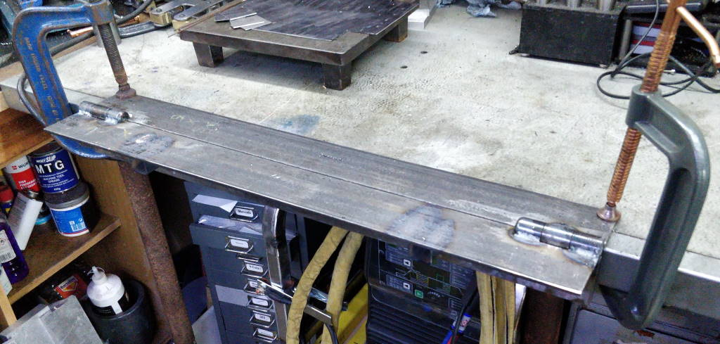
This is a bender I've made for bending sheet metal, for example for making drawers or boxes. It is loosely based on an idea by Rick Sparber, although I chose to make the hinges in a slightly different way to suit the material I had available.
The main part of the bender is made from 75 mm × 75 mm × 6 mm angle iron. I bought a 1.5 m length of it and cut it in half to make the two "jaws" of the bender. The hinge bodies are made from 25 mm diameter EN3B; the hinge shaft is 12 mm diameter silver steel.
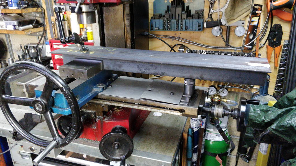
This photo shows the two jaws in the mill vice (with the other end supported by my Machinist's Jack). I used a dial indicator to ensure the top surface was level with the travel of the table X-axis (this can be seen in the photo: like all photos on this site, click on the photo for a bigger view).
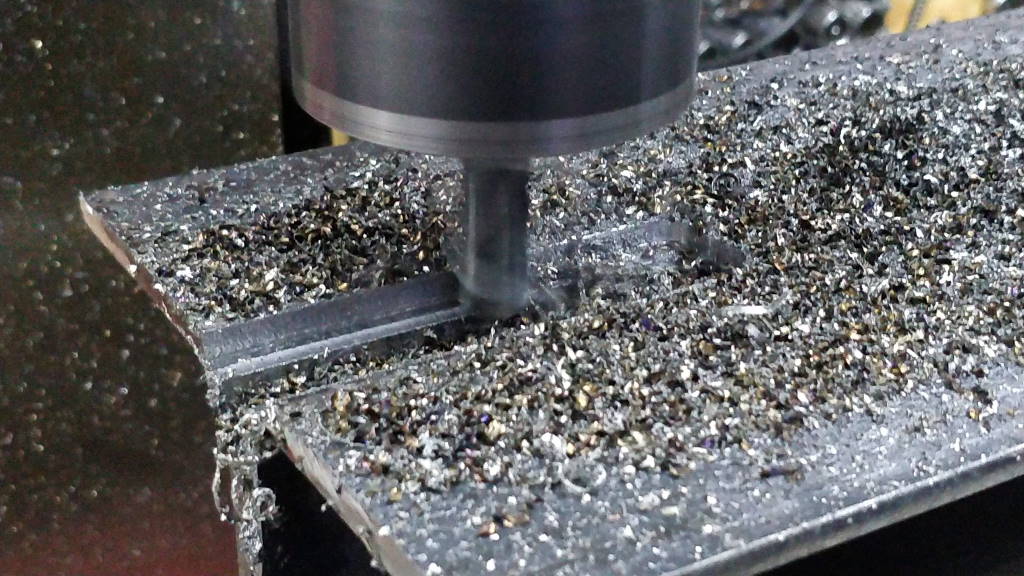
I then used a 12 mm end-mill to cut a 25 mm wide, 12.5 mm deep slot in the two pieces of angle iron, ensuring that the slot was cut equally into each piece (this ensures that the axis of rotation of the hinge is at the corner of the two pieces of angle iron).
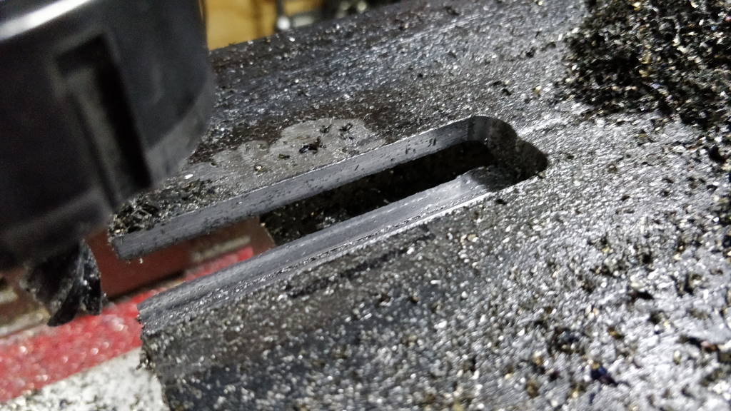
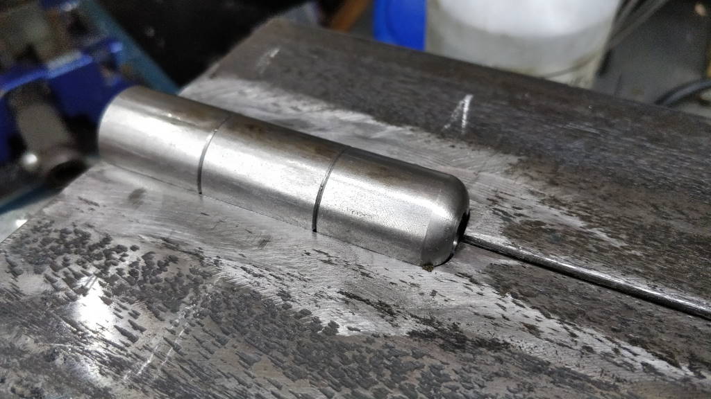
This photo was taken straight after finishing one of the slots. The end in the top-right of the photo has a 6 mm radius due to the shape of the end-mill. It looks in the photo that the end of the cut isn't square, but this is just a photographic oddity: it doesn't look like that in real life!
This photo shows the hinge parts inserted into the slot and ready for welding. A small gap (not visible in the photo) was left between the hinge body parts to ensure that they wouldn't rub. The right-hand hinge body had one end radiused using a 6 mm corner-rounding end mill held in lathe tool holder. This matches the radius of the slot. Not visible in the photo is the silver steel hinge shaft, which was inserted into the hinge bodies prior to welding to ensure that they stayed in alignment.
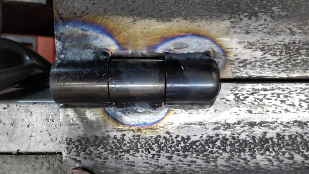
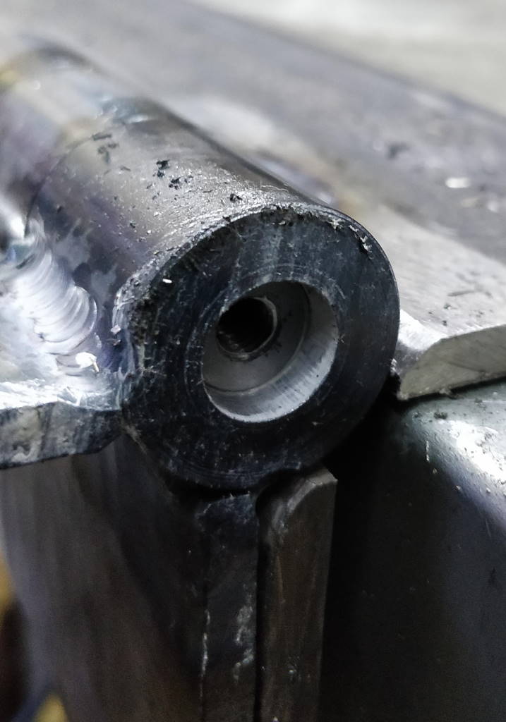
These two photos show a close-up of the hinge after it had been TIG welded in place. The right-hand photo shows the silver steel hinge shaft, which has an M6 hole threaded in the end. This hole is there to make it easier to get the shaft out if required. The white stuff in the photo is white lithium grease, which got everywhere when I was inserting the shaft!
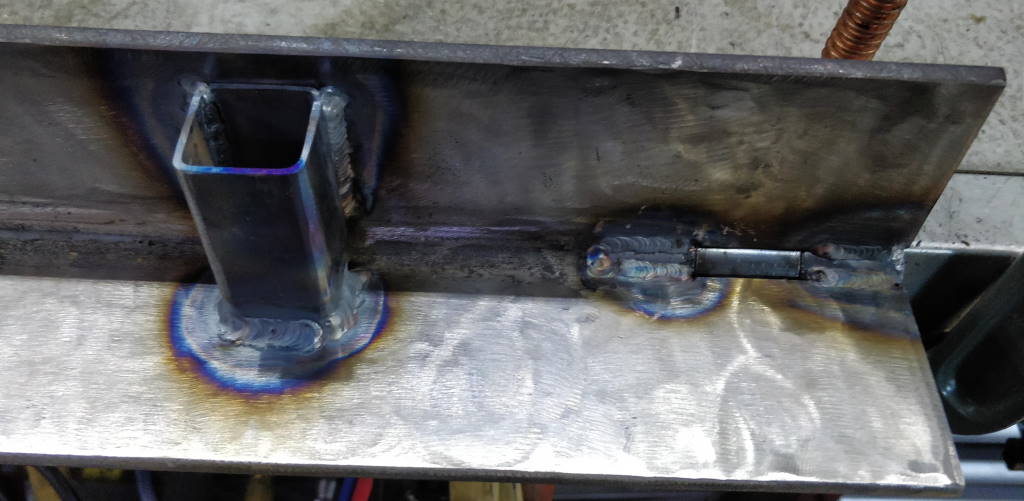
This photo shows the underside of one end of the moving "jaw" of the bender. On the left of the photo, you can see a piece of 30 mm × 30 mm × 2 mm box section that has been welded onto the moving jaw in two places. I can then use 25 mm × 25 mm × 2.5 mm box section as lever arms as they fit smoothly into the welded-on box section.
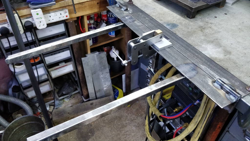
This photo shows the set-up for my first ever bend with the bender. I was bending a small square piece of 0.8 mm mild steel cut out of the corners when preparing a flat pattern for making a box. The sheet metal is held in place with a scrap of aluminium and one of my home-made Cantilever Clamps. You can see the 25 mm × 25 mm × 2.5 mm box section arms used as levers.
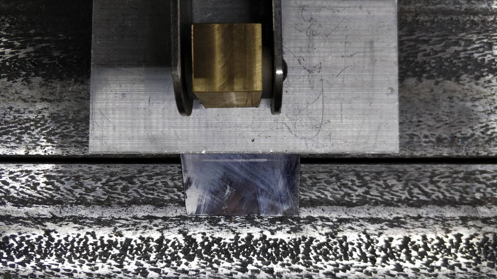
This is a close-up of the set-up for the first bend. The aluminium clamp block is set back slightly (2.5 mm in this case) from the centreline of the two "jaws". This is to allow for the radius of the bend.
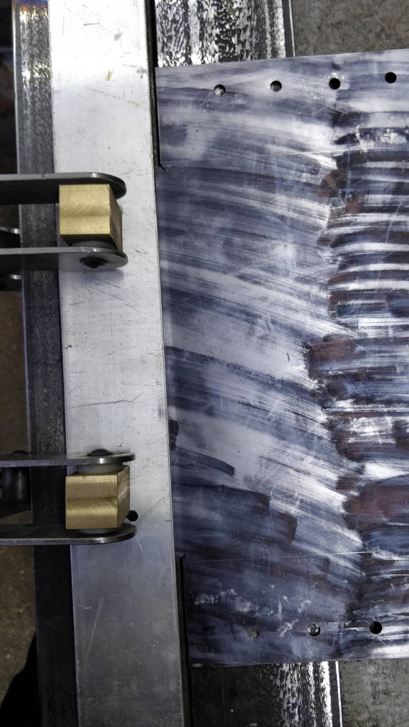
This photo shows the set-up for my first bend of a box pattern. The inky pattern is just some marker pen I used to mark up the box pattern; the clamping bar is another piece of aluminium I had lying around.
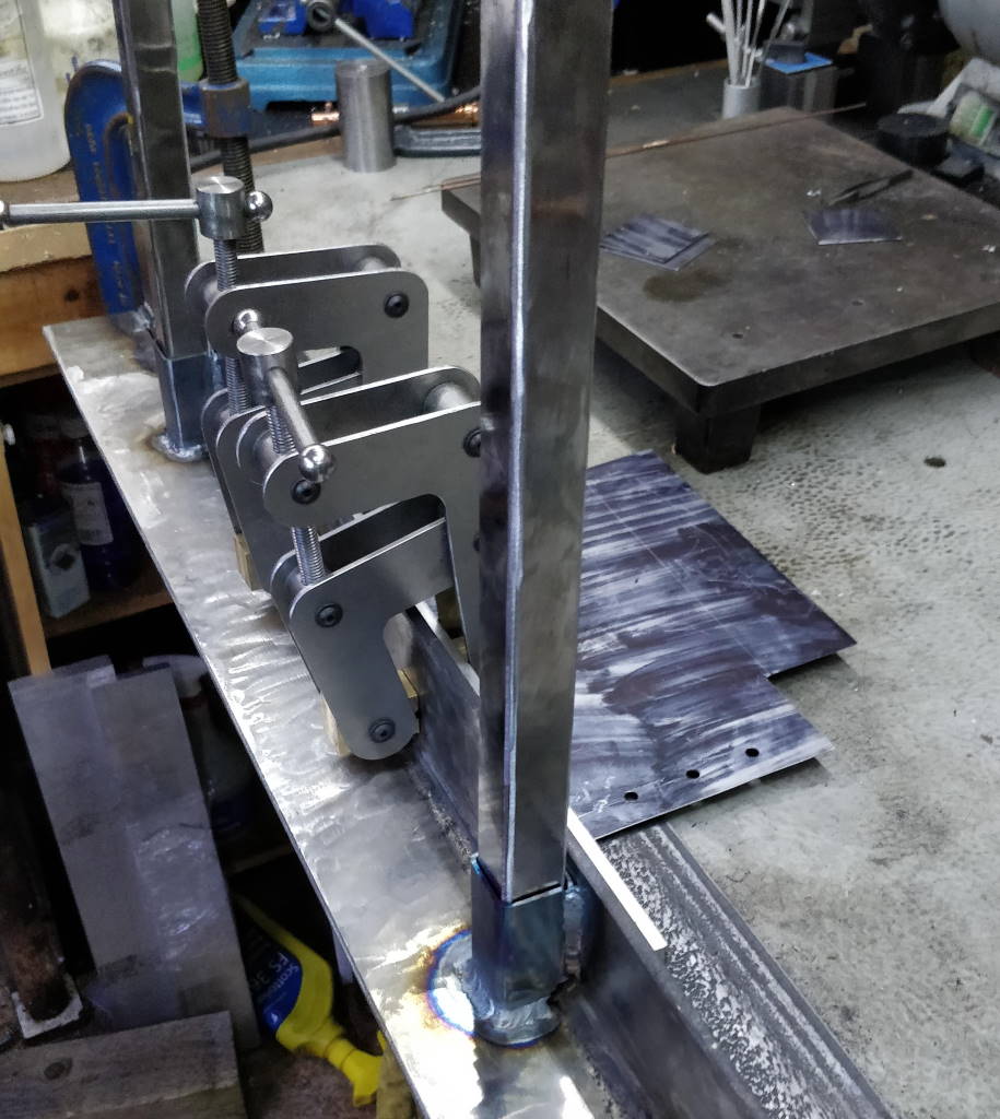
This shows the position of the bender just after completing the first bend for the box. The effort involved in bending 0.8 mm mild steel is minimal.
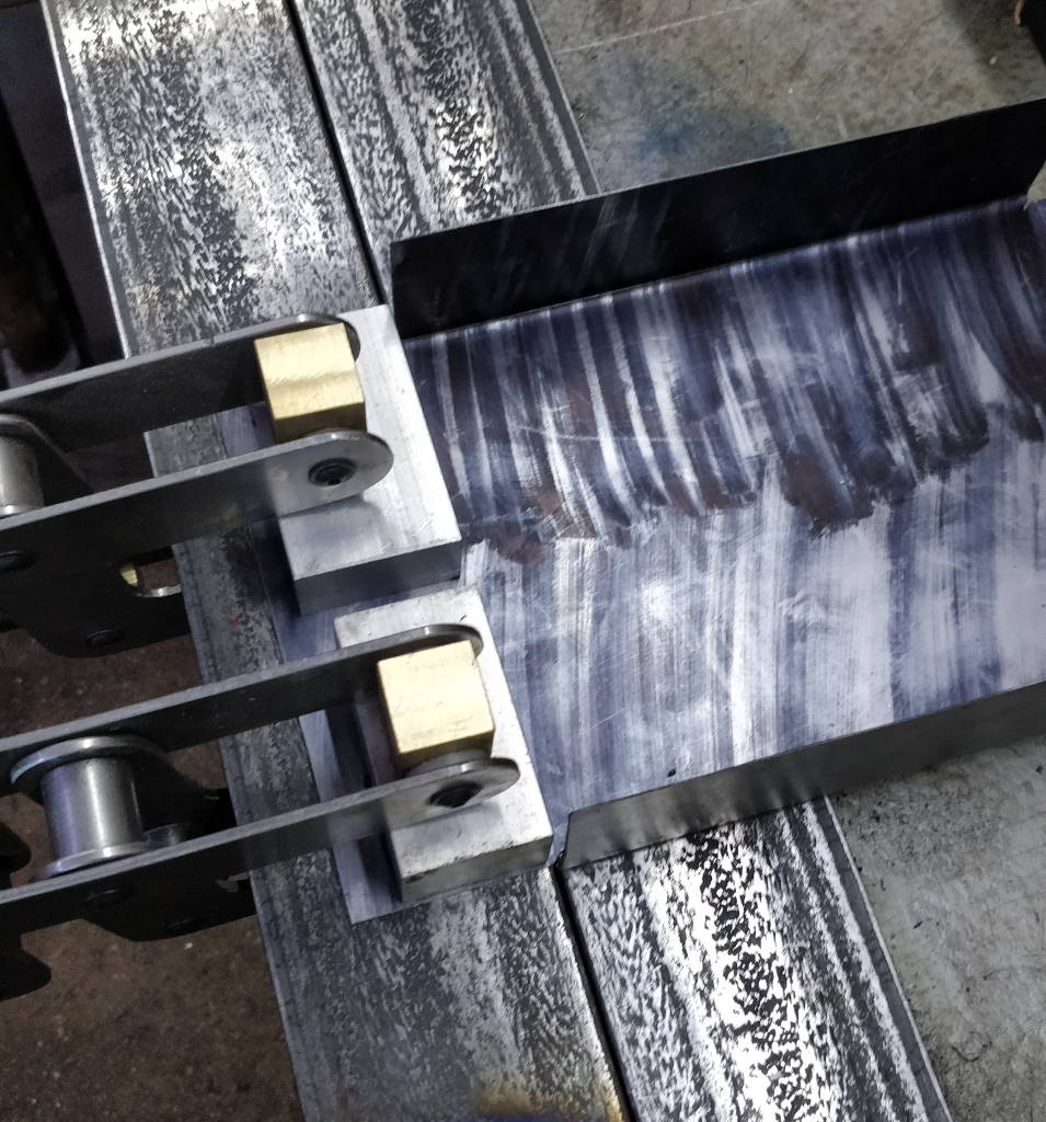
Once the first two outside bends are completed using the long clamping bar, a slightly different clamping method is required. This photo shows a couple of small blocks of aluminium used as "fingers" for the third bend. They were chosen as together they were slightly shorter than the width of the box and so fit inside the previous bends.
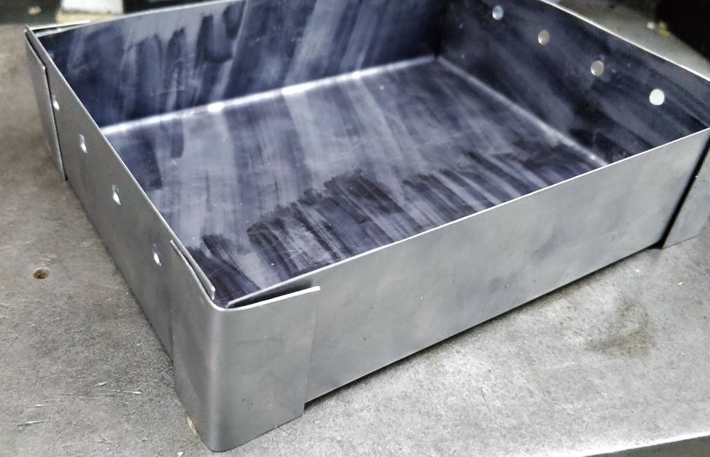
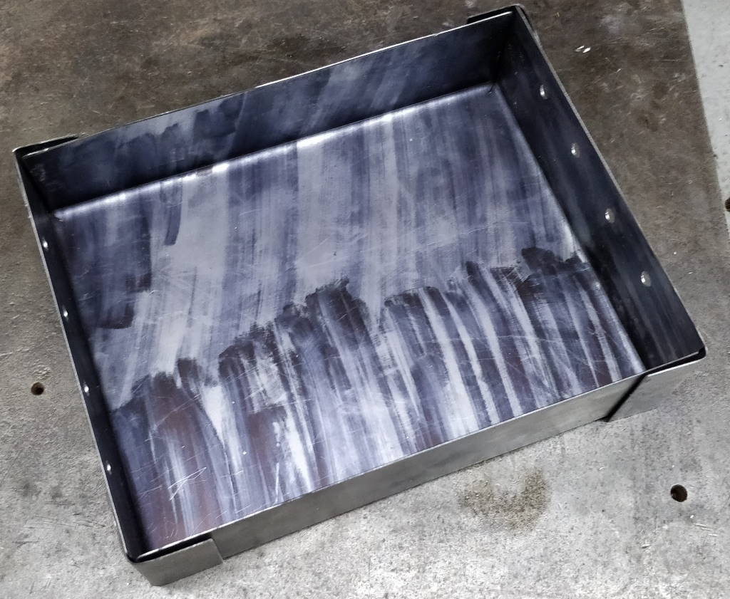
These photos show the (nearly) finished) article. The corner reinforcing pieces are made from the cut-outs of the pattern. Once all the marker pen has been cleaned off and I've had a bit more practice TIG welding thin metal, I'll weld the reinforcement pieces in place and the tray will be complete.
Update
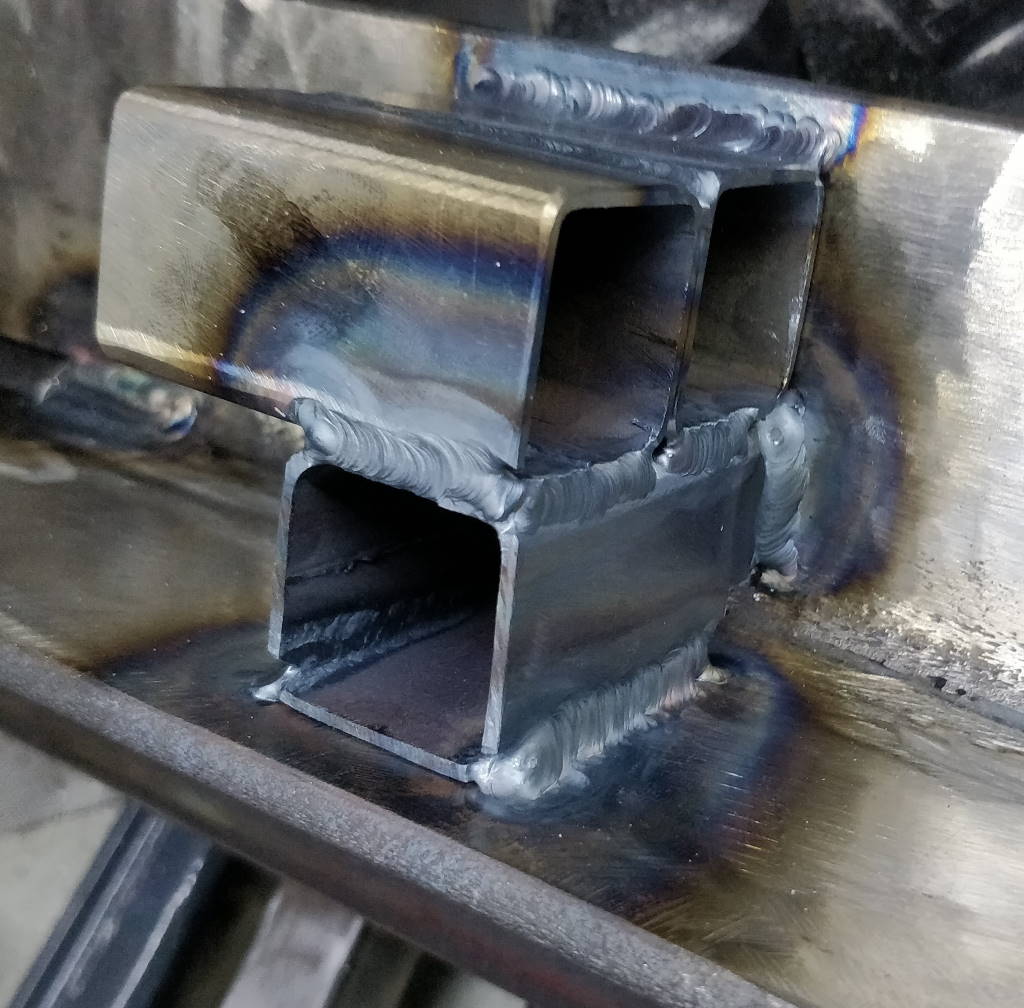
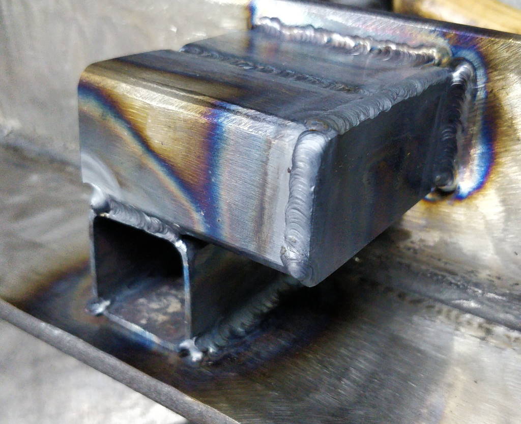
When not in use, the bender has a home leaning up against a drawer unit in my workshop. The lever arms just lean up against it. I've been finding that they have a habit of falling over and either/or hitting things or just getting in the way. I had a few off-cuts of 30 mm × 30 mm × 2 mm box section, so I decided to weld these on top of the existing bits of box section on the welder. On one end (shown in the right-hand photo above), I added an end plate from some 3 mm steel.

Now the lever arms have somewhere to go when the bender isn't being used.
This website is free and ad-free, but costs me money to run. If you'd like to support this site, please consider making a small donation or sending me a message to let me know what you liked or found useful.
