Mini Moravian Bench Build Process
Page 8 of 38
Posted 6th July 2025
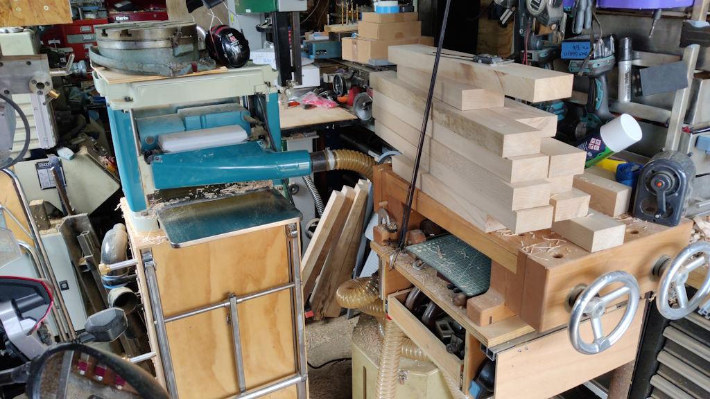
I started the morning (after playing with CAD a bit) by using the thicknesser to bring the legs and the cross pieces down to 40 mm thickness. I did that in the garage, which isn't quite as ergonomic as doing it in the garden, but it does save trying to manoeuvre the thicknesser trolley over some rather rough ground en route to the garden. This is what the set-up looks like in the garage:
While thicknessing, I stand on that little bit of clear ground you can see to the right of the thicknesser trolley. I put all the planks on the bandsaw table and then feed them in with one hand, catch them with the other and put them on the portable workbench. It works, but it isn't ideal.
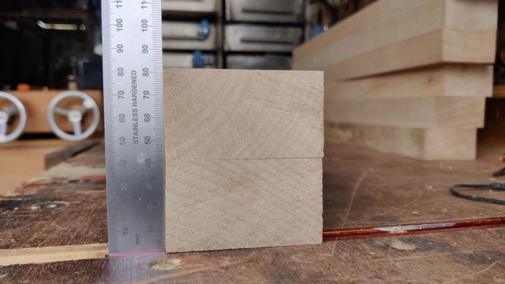
With all those pieces reduced in size, I could stack a couple of leg halves up to get a sense of scale:
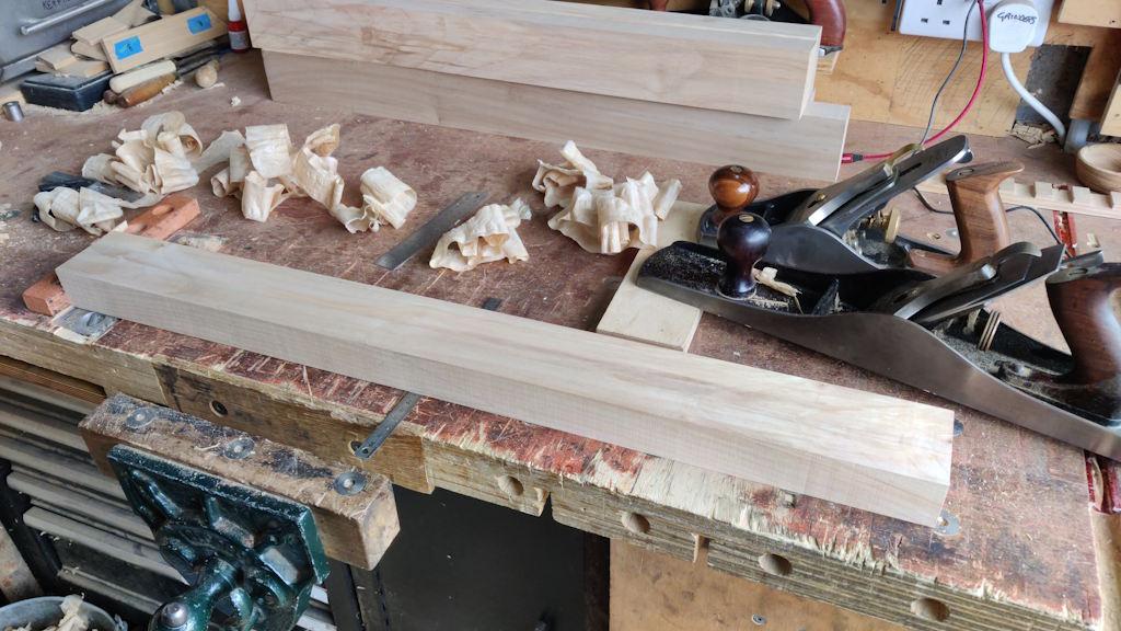
It was then time to deal with the machine marks from the thicknesser. For now, I've just done one face of each board:
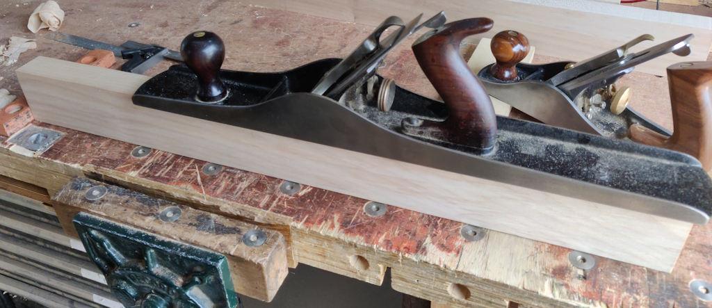
... and one edge:
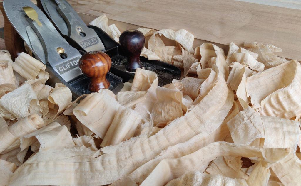
With the heat (and the fact that Sycamore takes a bit more effort to plane than the Sweet Chestnut I've been using recently), I needed to take a bit of a break after each pair of legs, so I used one of those rest periods to get a photo of some plane shavings because, well, why not?
With all the legs planed on one face (which will become the inside of the leg) and one edge (which will become the inside edge), I could pair them up. I then wanted to get on and do a bit more work on one leg. I've tended to work on a single part when doing something relatively new: do one part as far as I can, then do all the others at the same time. That way I'm less likely to mess all the parts up in one go!
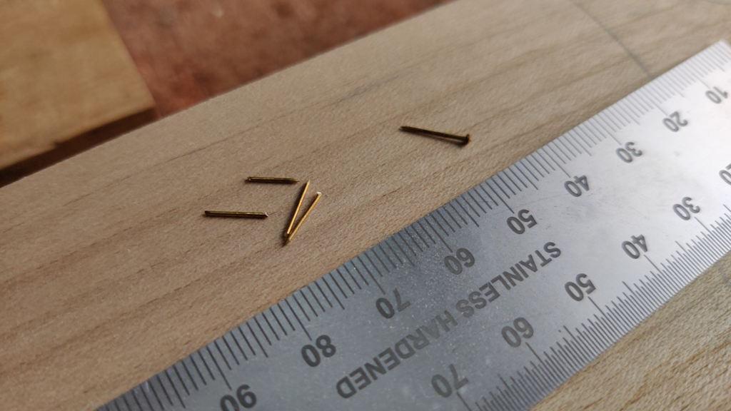
Having decided which one goes with which, I got some small brass pins and chopped the heads off:
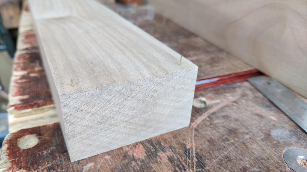
I then tapped two into each end of one of the leg halves (very near the end: the bits of wood they're in will get cut off when the legs are cut to length):
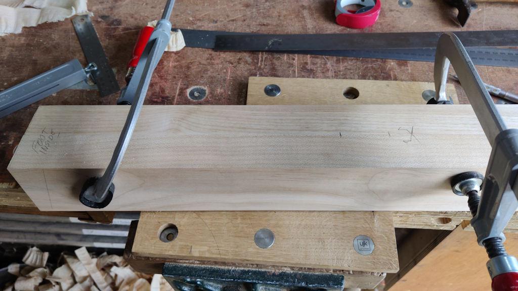
The halves for that leg then got clamped together and I took a quick pass with a smooth planing to make sure the (pre-planed) edges were flush (the opposite edge is still quite rough at this point):
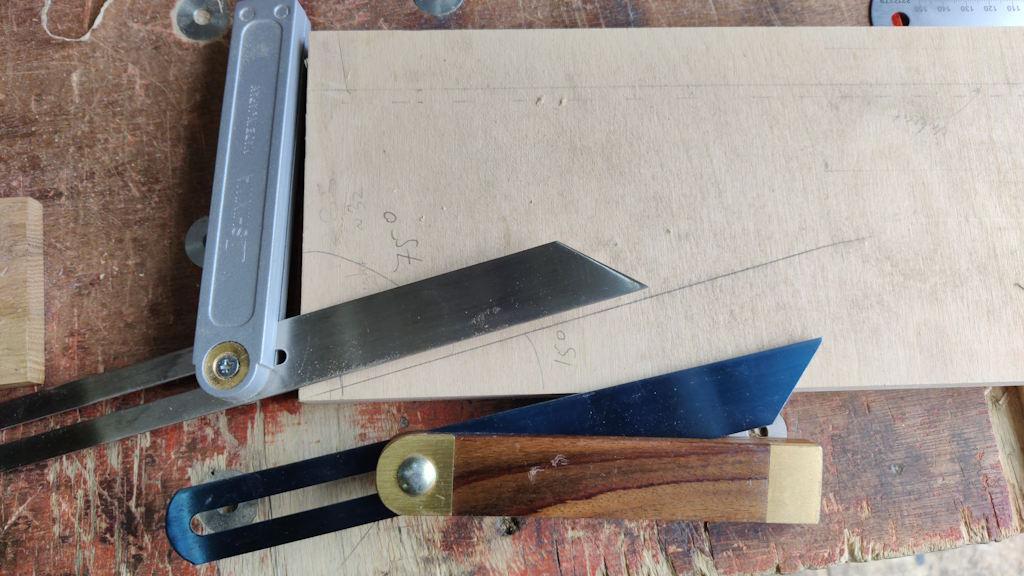
I dug out a bit of plywood with a 90° corner and marked a line on it at 15° to the long edge. I then used that to set up a pair of sliding bevels, one at 75° and one at 15°. I'm not sure that I need the 15° one yet, but I figured it was a sensible thing to do while I was setting the other on up.
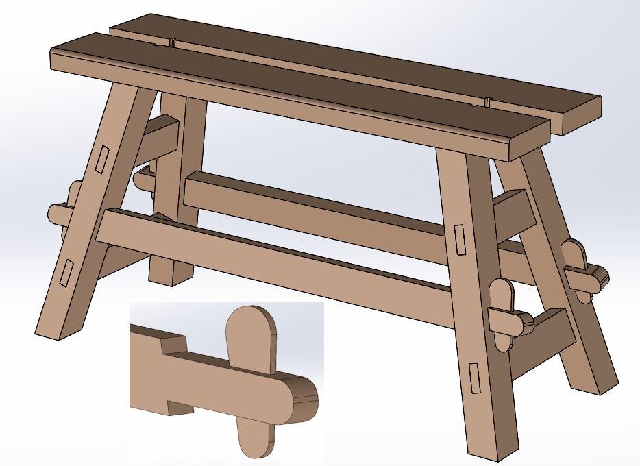
The CAD model has changed a little (although you'd have to look carefully to spot it!) from the last time I shared it:
The main differences are that I've moved the stretchers slightly lower and I've changed the stretcher tenons to be bare-faced (as you can see in the inset image). Given the lack of a face shoulder, I also increased the size of the edge shoulders to 15 mm. With those changes made, the CAD model could be used to work out where the mortice needs to go in the leg.
The next job was to decide which end of the leg was the foot and mark the bottom end angle (in roughly the right place, but not worrying too much about precision at this point). I could then mark two positions: one 265 mm up from the heel and one 45 mm further up from there.
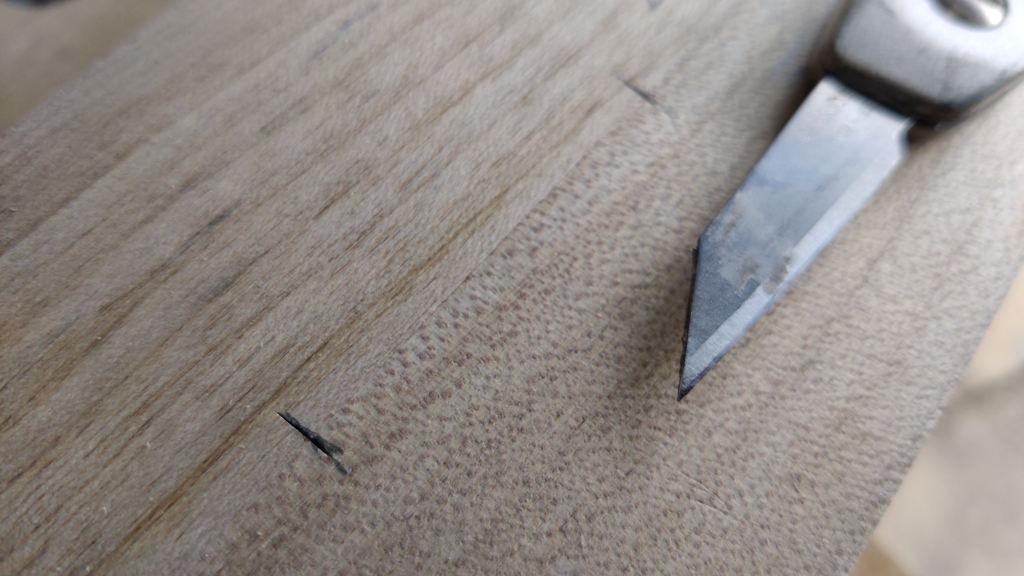
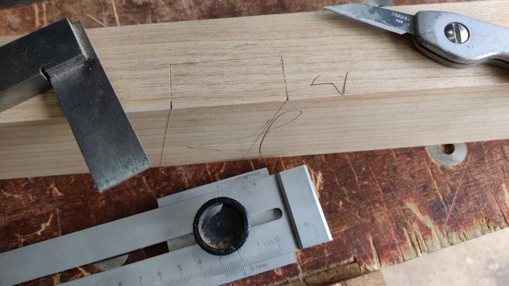
Those two positions got marked across the join line with a knife:
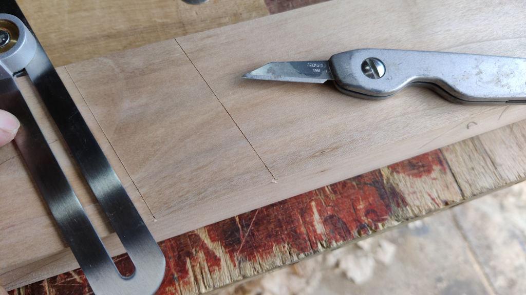
The sliding bevel (set to 75°) could be used to mark the shoulders of what will be a mortice:
A square and an edge distance gauge thing marked the depth of the mortice (20 mm in each half to match the 40 mm thick stretcher):
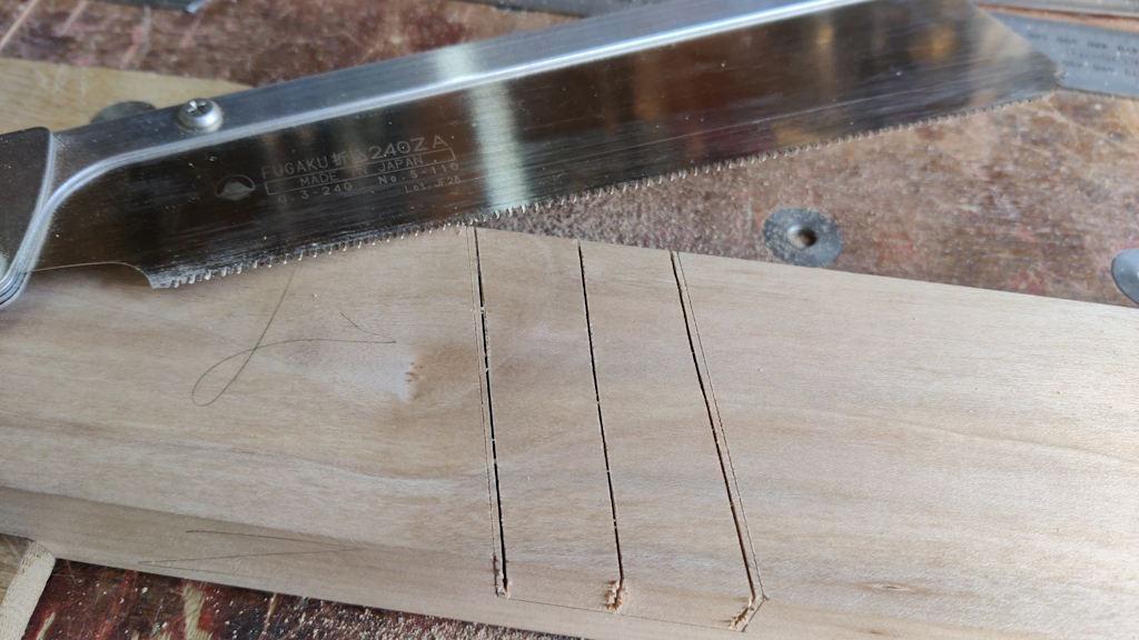
It was then a fairly simple process of sawing...
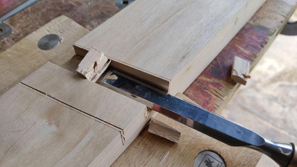
... chiselling...
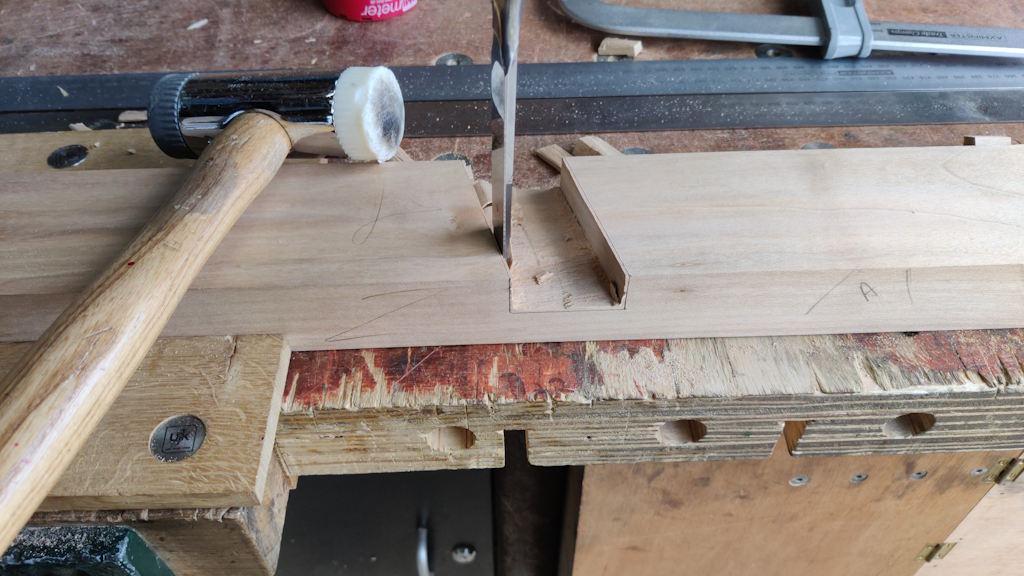
... and then two of my favourite woodworking jobs: chopping shoulders...
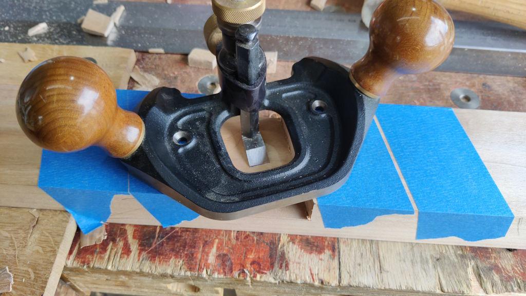
... and router planing (with the depth stop set for a consistent depth on each half):
The masking tape is there just in case any wood chips get underneath the router plane base: they'll tend to tear the tape (which will be obvious) and are less likely to damage the glue face.
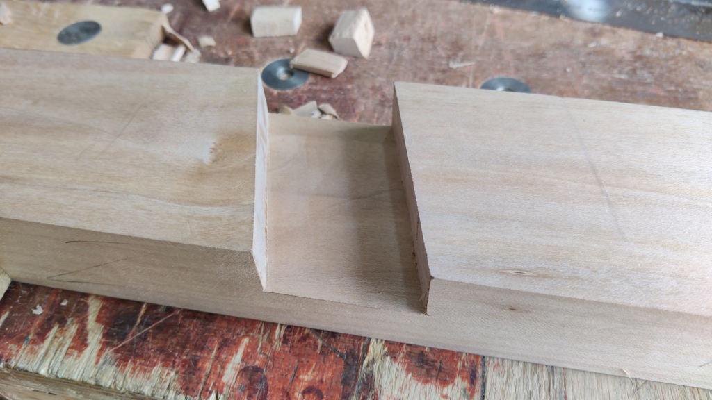
One half done:
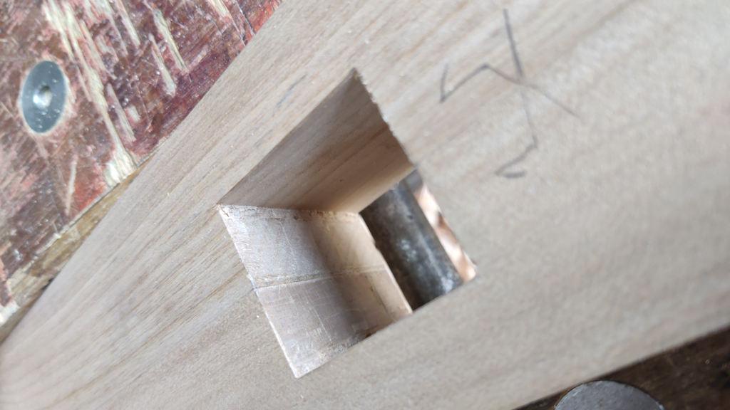
After lining the brass pins up with their corresponding holes, I could push the two leg halves together and I was very pleased to see the mortice sides lining up nicely:
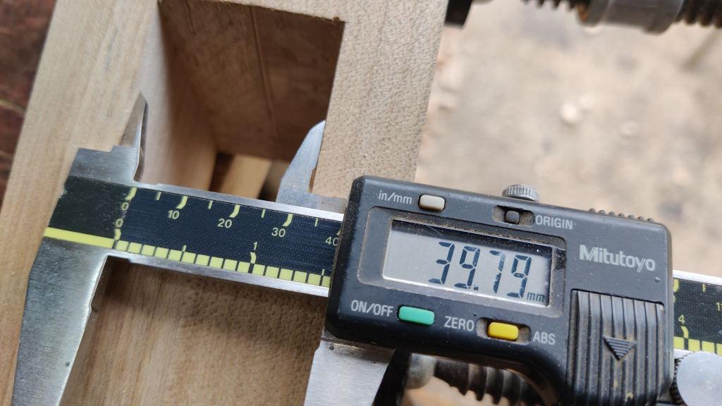
The size is also about right:
The stretchers are currently a shade over 40 mm and the hole is a shade under, which felt right to me. Once I've got all the legs glued together, I can plane the stretcher faces slightly to get a nice fit (probably very slightly undersize to allow for expansion of the stretcher).
I could probably glue that leg together now, but I don't think there's a rush really so I'll probably do all four at the same time once all the stretcher mortices have been cut.
Page 8 of 38
This website is free and ad-free, but costs me money to run. If you'd like to support this site, please consider making a small donation or sending me a message to let me know what you liked or found useful.

 Return to main project page