Portable Workbench Build Process
Page 36 of 67
Posted 21st March 2021
Well, so much for "no more metalwork"… but more on that later.
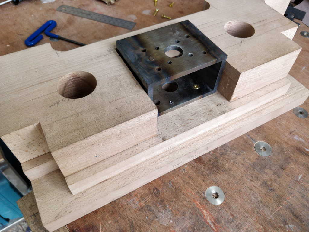
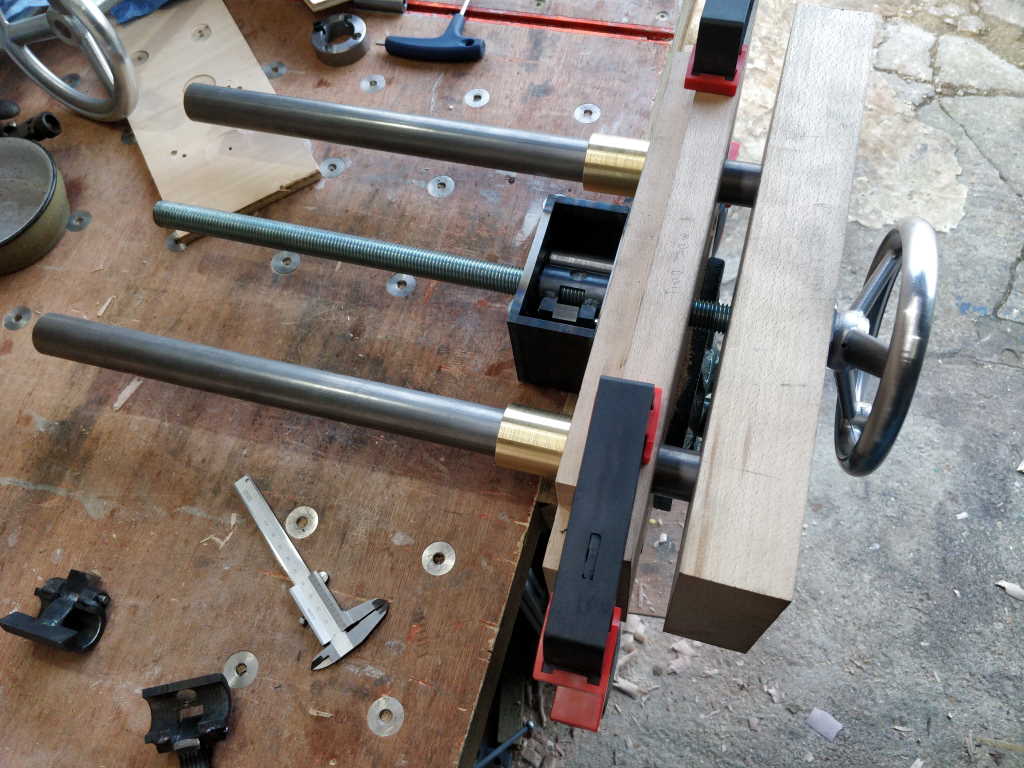
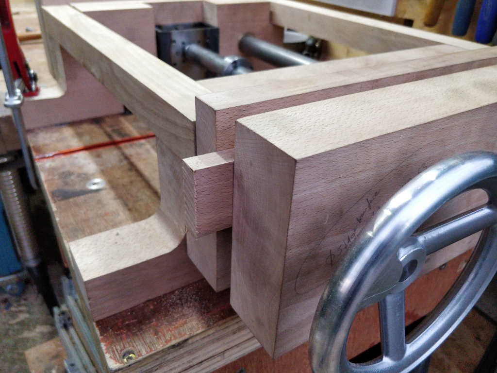
This afternoon I started by working out how much extra space was needed for the vice mechanism. To do this, I fitted the vice mechanism to the fixed jaw and slid the foot up as far as it would go:
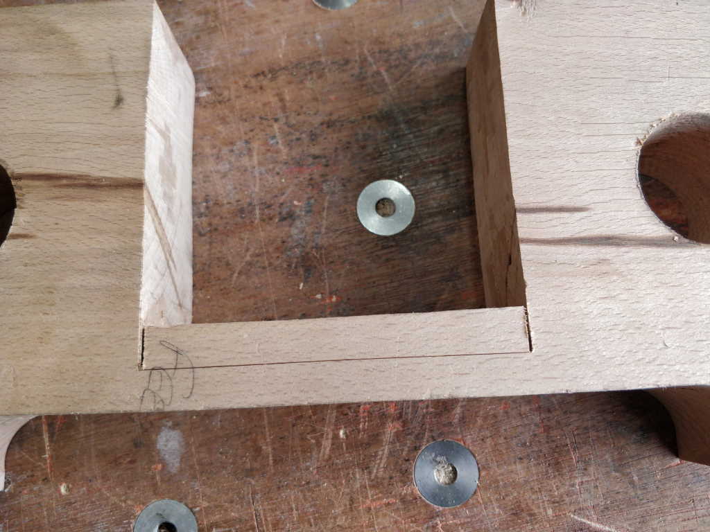
I could then measure how much the foot needed to move to get to the right place and therefore how much material to take away. Then I could mark it up and saw down the sides:
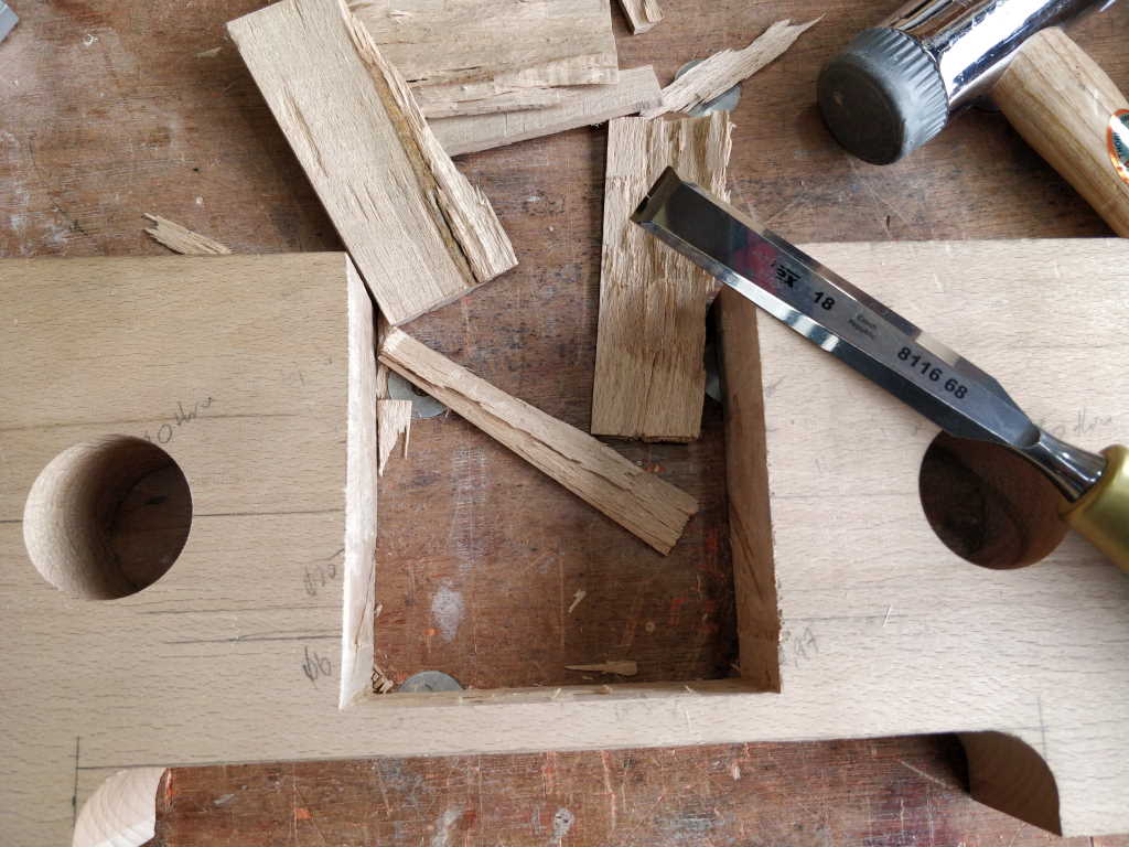
Chopping the material away was very quick as I was cutting along the grain:
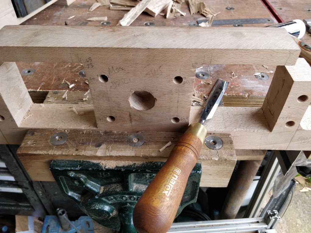
Finally, I pared the bottom down to make it a bit neater (although it'll be hidden under the vice mechanism so it's not too important how it looks):
Having screwed the vice mechanisms to the fixed jaws, it seemed a good point to try one out with all the metal bushes / bearings etc in place. That's where I found that the vice mechanism didn't work. Lots and lots of profanity ensued.
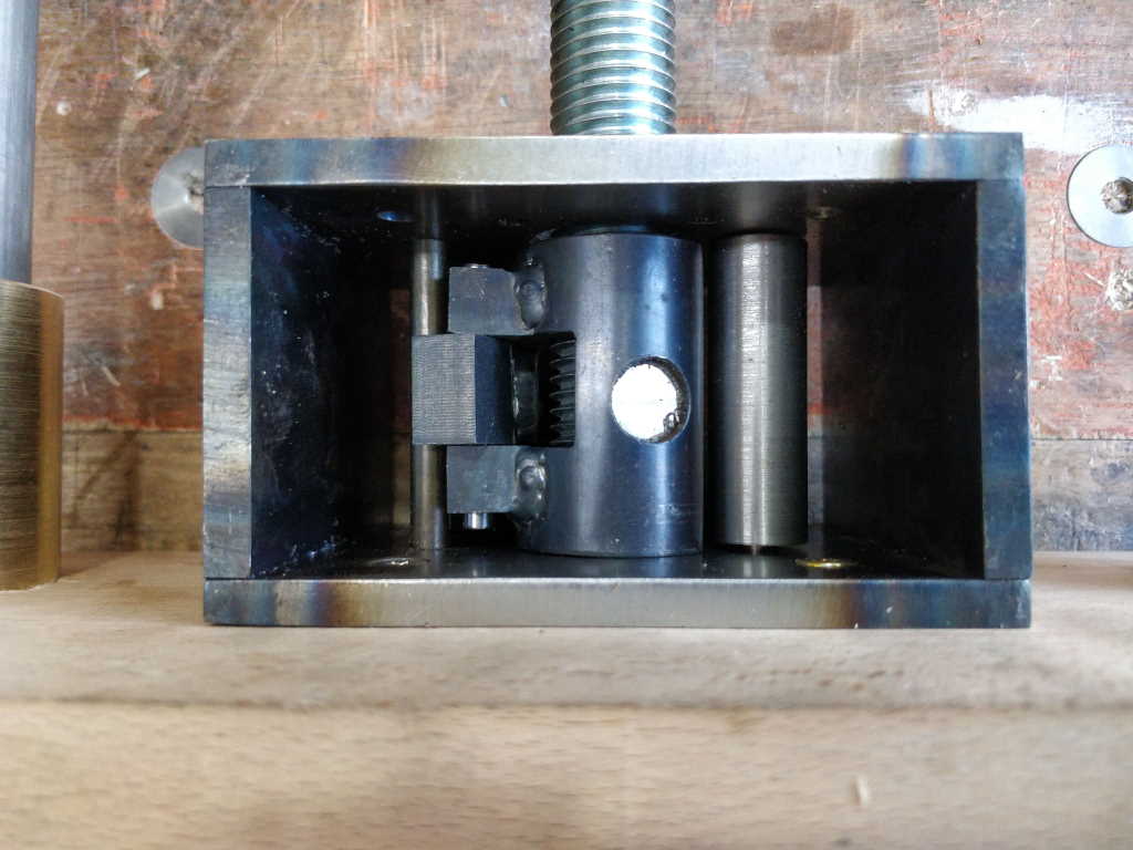
When I made the original vice mechanism prototype over Christmas, I did lots of testing to make sure it worked consistently and could be tightened very tight. When I modified the design to make it fit into a smaller space, I just checked it engaged and disengaged but didn't do any further testing. That was a mistake! What seemed to be happening was the geometry of the tube, the hinge bar location and the nut were such that as it tightened, the tube lifted off the threaded rod, which allowed the nut to drop away from the threaded rod.
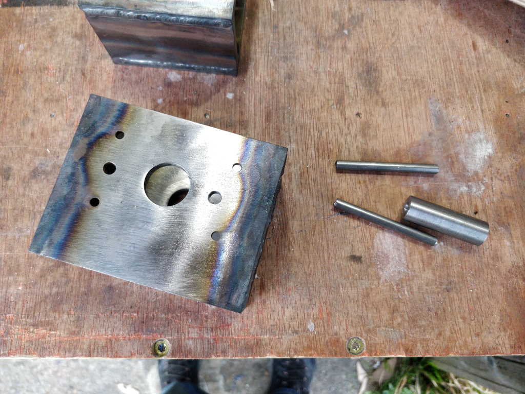
After lots of messing around with various random scraps of material I had lying around, I worked out that all that was needed was something that would stop the tube from lifting when it was at the angle it sits when locking. I put one of the vice mechanisms back in the milling vice and drilled another 6 mm hole through both sides of the mechanism. I then turned a simple tube, 15 mm OD, 6 mm ID to sit on the new shaft and act as a stop.
The reason I went with a 6 mm shaft with a separate part sitting on it was it gave me room to tweak the diameter if it didn't work. I'm glad I did as for some reason I can't quite work out, one of the mechanisms needed a 16 mm tube instead of a 15 mm one. I presume it must be something to do with the location of the hinge bar (which is arbitrary) as I'm fairly sure I drilled the hole in the right place!
With this modification, the vice is rock-solid and clamps bits of wood extremely robustly. Phew!
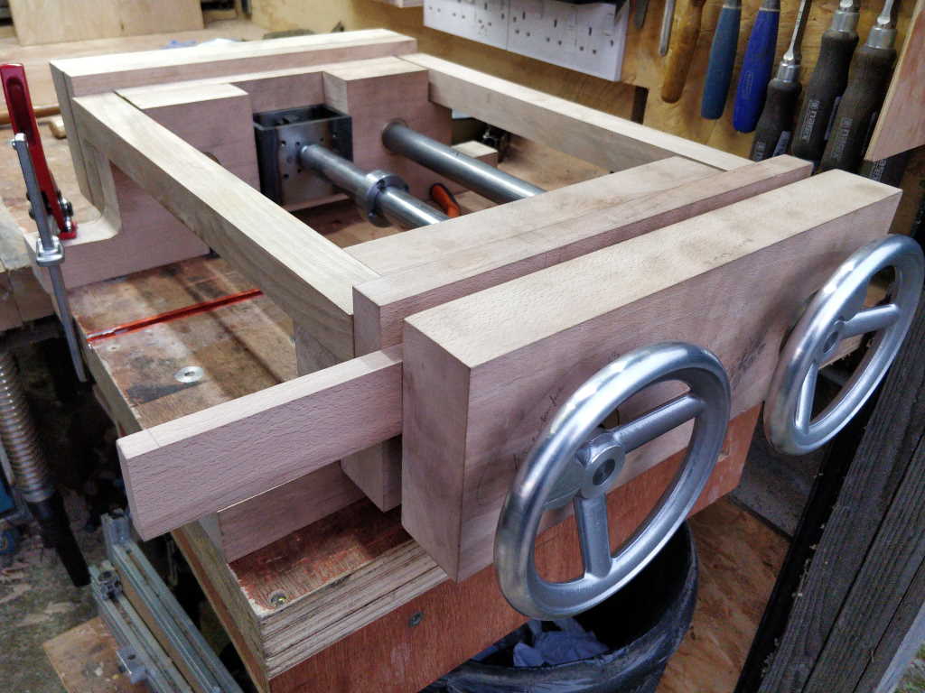
Anyway, with all the vice mechanisms modified and working well, I put the whole lot back together and clamped a random bit of wood in the dual-screw vice:
and cut the end off!
That was amazingly satisfying for such a simple job!
This isn't really the purpose of the dual-screw vice (I'd usually use the standard vice for this sort of cut), but I'd assembled it with that end facing out so I figured it would do.
If you look closely at those last two pictures, you'll notice that I've clamped one of the feet down to the workbench. It's a sign of the heft and hence stability of this thing that it didn't wobble at all, even though the end I was using wasn't attached (apart from via the screw threads going loosely through the holes in the rails for the other vice) to the bit that was clamped down.
I'm a much happier bunny now than I was when I realised it wasn't clamping properly!
Page 36 of 67
This website is free and ad-free, but costs me money to run. If you'd like to support this site, please consider making a small donation or sending me a message to let me know what you liked or found useful.

 Return to main project page