Salt & Pepper Mills Build Process
Page 3 of 11
Posted 10th March 2025
The Law of the Instrument states something along the lines of "if all you have is a hammer, everything looks like a nail". I think a similar (but perhaps less aggressive!) sentiment can be expressed for the metalworking lathe and the 3D printer in that when you have a lathe/printer, every problem looks like it can be solved with that tool.
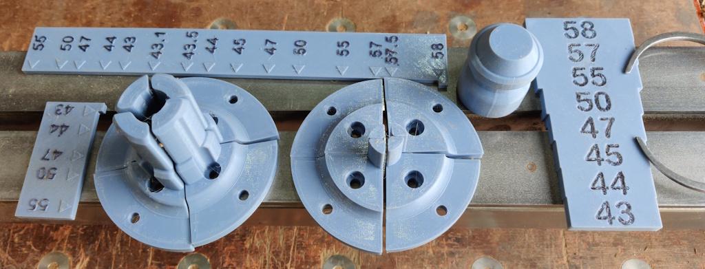
Despite this being a woodturning project, both the printer and the metalworking lathe have been used. Here's a photo of a few of the 3D-printed bits and bobs I've made for this project. Some of these have been replaced with newer versions or alternatives, but we'll get on to that later.
Jaws for woodturning lathes are quite expensive. I got most of mine quite cheaply (£10 to £15 a set) from an antique shop in Devon, but nevertheless I'd pondered idly whether it would be viable to print jaws and hence get fully customised jaws for next to nothing. The obvious concern is that plastic is much weaker than the steel that a jaw would typically be made of, especially considering that the sensible printing orientation for jaws is such that they could easily break along the join between the base and the bits that stick out.
Nevertheless, I was feeling quite confident about the jaws for turning the body: the shape that sticks out from the jaws is primarily serving the purpose of centring the body and hence isn't working that hard. The tailstock support will be pushing the body firmly up against the flat part of the jaws and the induced friction from that pressure provides the motive force. 3D-printed objects are generally very strong under compression.
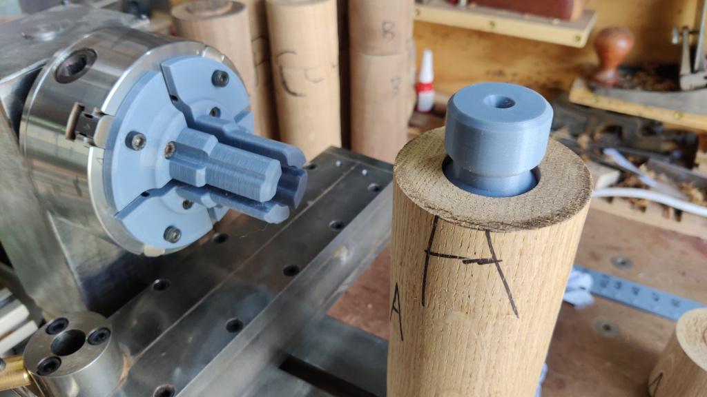
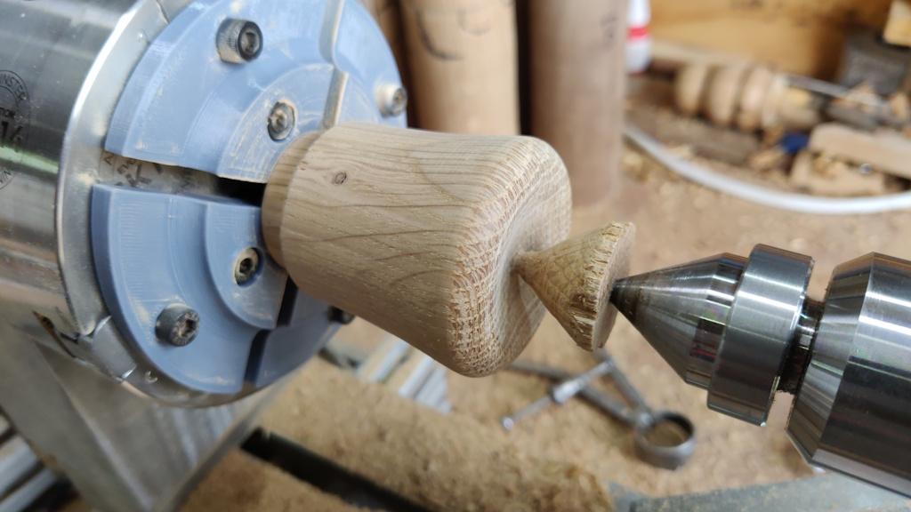
To centre the body at the tailstock end, I'd printed a 35 mm diameter "plug" with a 60° hole in the bottom for the live centre to sit in:
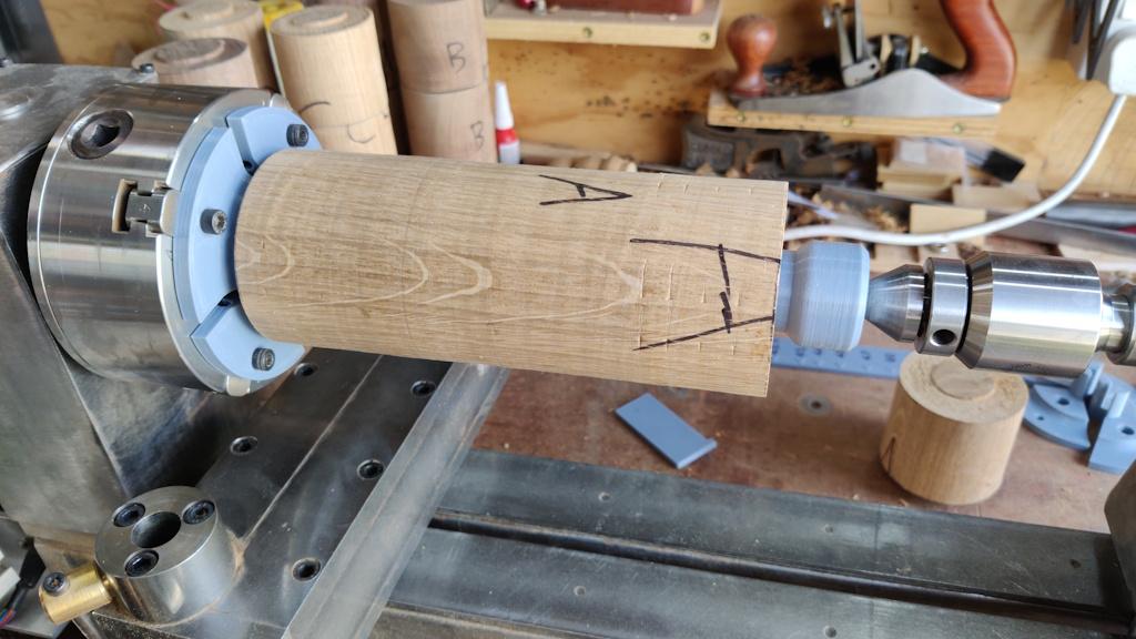
This is what it looks like all mounted on the lathe:
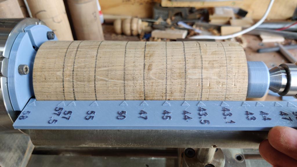
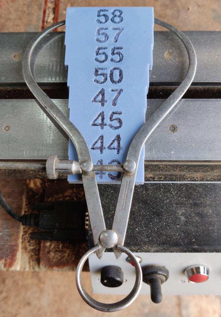
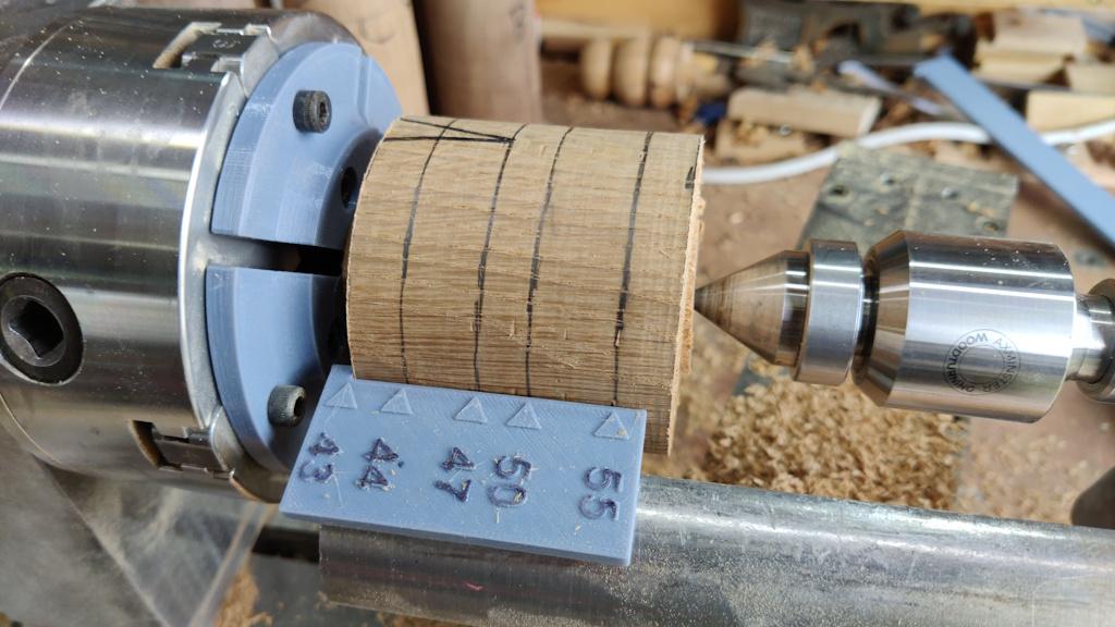
Having drawn the target shape in Solidworks, I'd used that shape to make a simple guide plate to help identify and locate some key diameters along the length and I used that plate to mark a few positions along the cylinder with a pencil:
I largely ignored the decimal places on the plate (there's no way I'm going to be working to anywhere near that precision: I'd be lucky if I'm accurate to a millimetre!), but since I was printing it out I figured I might as well show the target size.
I'd also printed a simple setting gauge with the various diameters on it (and with a tenon on the back that's a tight fit in the gap between the ways on the lathe so it stays put at the end of the bed). This gets used to quickly set my (only set of) outside calipers:
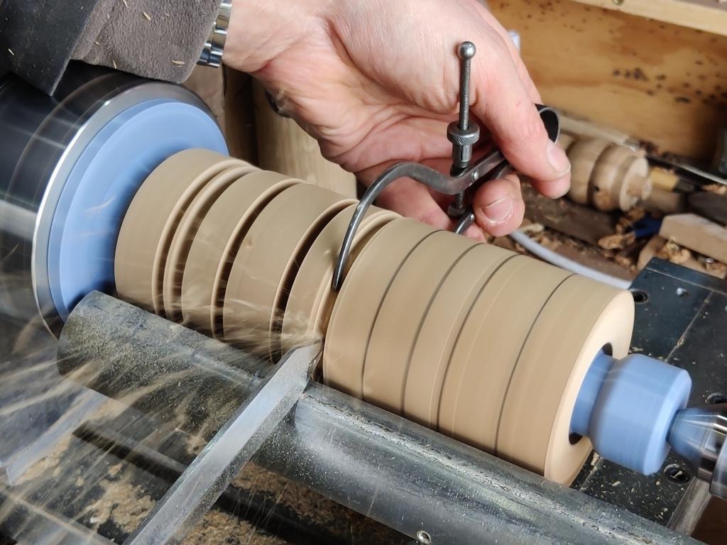
The calipers then get held over the pencil lines and the parting tool plunged in until the calipers pop out the back...
and yes, my jumper is getting very close to getting tangled up by the chuck in that photo: my arm was there in order to keep it out of the way of the camera in the action shot; I usually keep it well out of the way. The jaws (by design) aren't protruding beyond the body of the chuck, so it's relatively safe anyway.
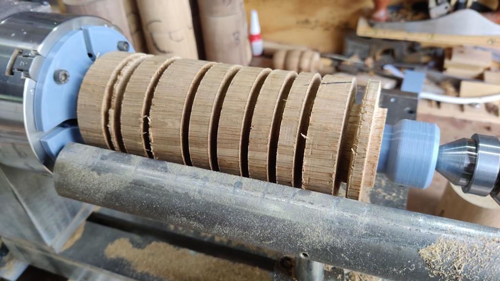
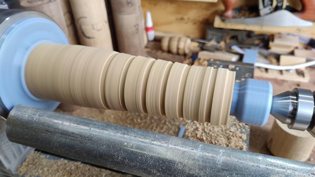
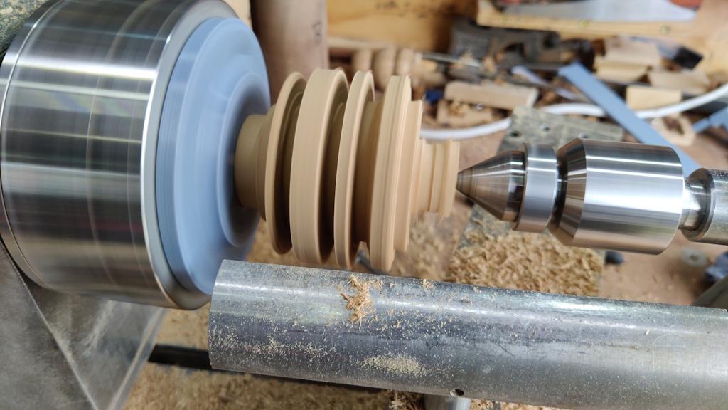
Turning all the set diameters left me with a blank that looked like this:
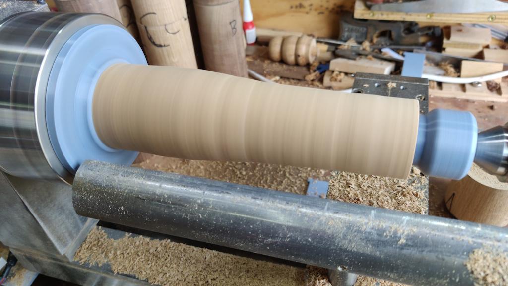
The spindle gouge then came out to blend the it all together:
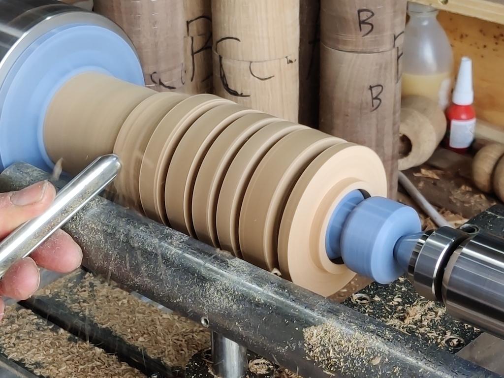
Part way through blending:
This is where I gave up on the gouge...
... and finished with sandpaper, starting at 80 grit and working through 120, 180, 240 and 320 grit.
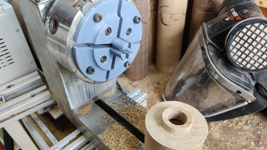
I had a lot less confidence in the custom jaws for holding onto the lid:
The narrow pins are providing the driving force (at least when the top of the lid is being shaped) and they're really quite thin and flimsy. I thought they were worth a try anyway (and, if I'd only be doing a single top, I think they would have been fine). Again, I started by marking out the diameter at a few key points:
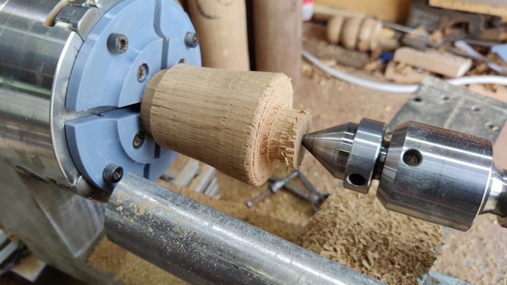
They got roughed down again...
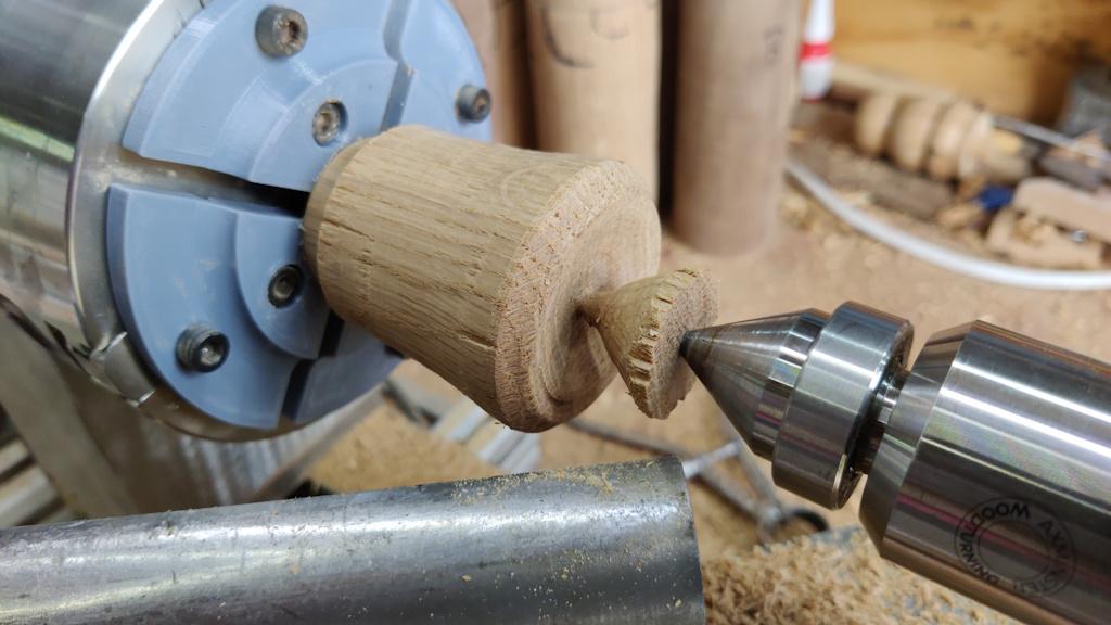
... and then shaped a bit more...
,.. and a bit more...
... and more...
The nub then got removed with a spindle gouge (this is where I was really relying on those flimsy jaws) and the end sanded:
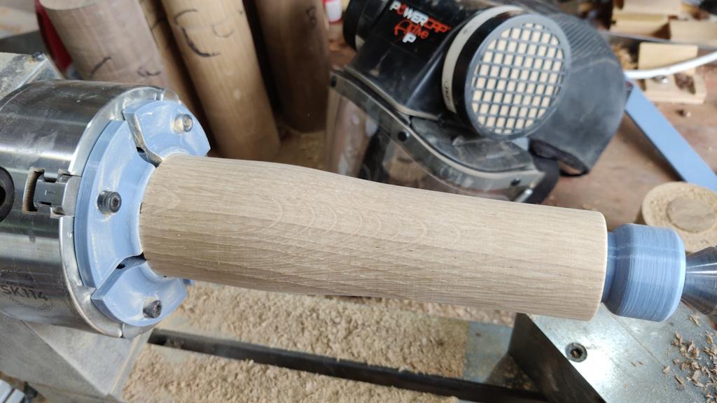
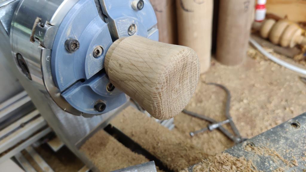
The body (which still hasn't got the mechanism fitted) looks okay-ish from this angle:
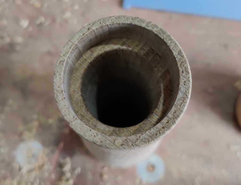
However, I was hoping for a bit more shaping on the lid and, if you look closely at the join between body and lid, you'll see it lines up at the bottom of the photo but not at the top. The reason for that is that the hole in the base part isn't concentric with the outside diameter, which you can perhaps see a bit better in this photo (compare the wall thickness in the top-left to that in the bottom-right)
When you hold the mill, it's very obvious (and it feels a bit weird when you try to turn the top). As a result, that one's getting added to the ever increasing scrap pile.
Page 3 of 11
This website is free and ad-free, but costs me money to run. If you'd like to support this site, please consider making a small donation or sending me a message to let me know what you liked or found useful.

 Return to main project page