Vice Handle Extension
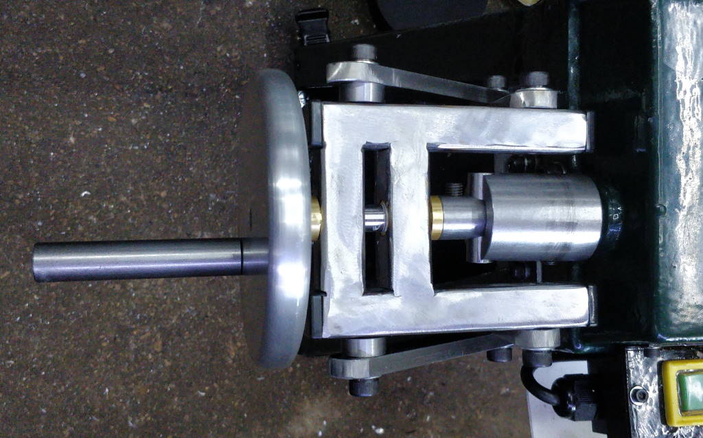
This is my (arguably somewhat over-engineered) new handle for the vice on the bandsaw.
The Problem
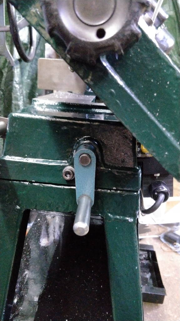
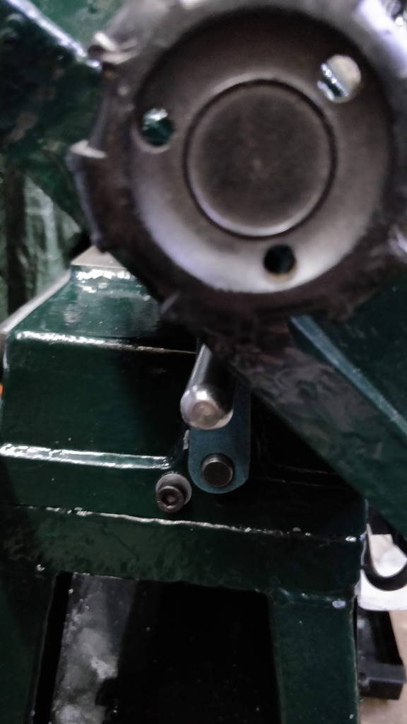
These photos show the original vice handle fitted to the saw. When the upper arm is horizontal (as it is when the saw isn't being used and as it always is at the end of the cut), the vice handle is hidden underneath the end of the upper casting and is very difficult to access. As a result, when a cut is finished, you have to lift the arm, release the vice, remove the work-piece and then lower the arm back down again. This was one of the things I found most frustrating about the bandsaw (after the flimsy base frame).
My original plan to solve this problem was to make an extended version of the original vice handle that would project out beyond the end of the upper arm. However, the leadscrew wobbles all over the place (I suspect it is quite badly bent) and hence extending the leadscrew exacerbates this effect. I therefore decided to go for a much more complicated solution.
Coupling
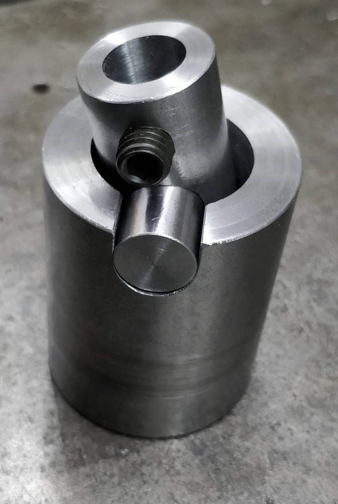
This photo shows a flexible coupling I made to isolate the motion of the leadscrew from the motion of the handle. It is made in three parts and is designed to allow angular misalignment in both planes and axial misalignment in one plane.
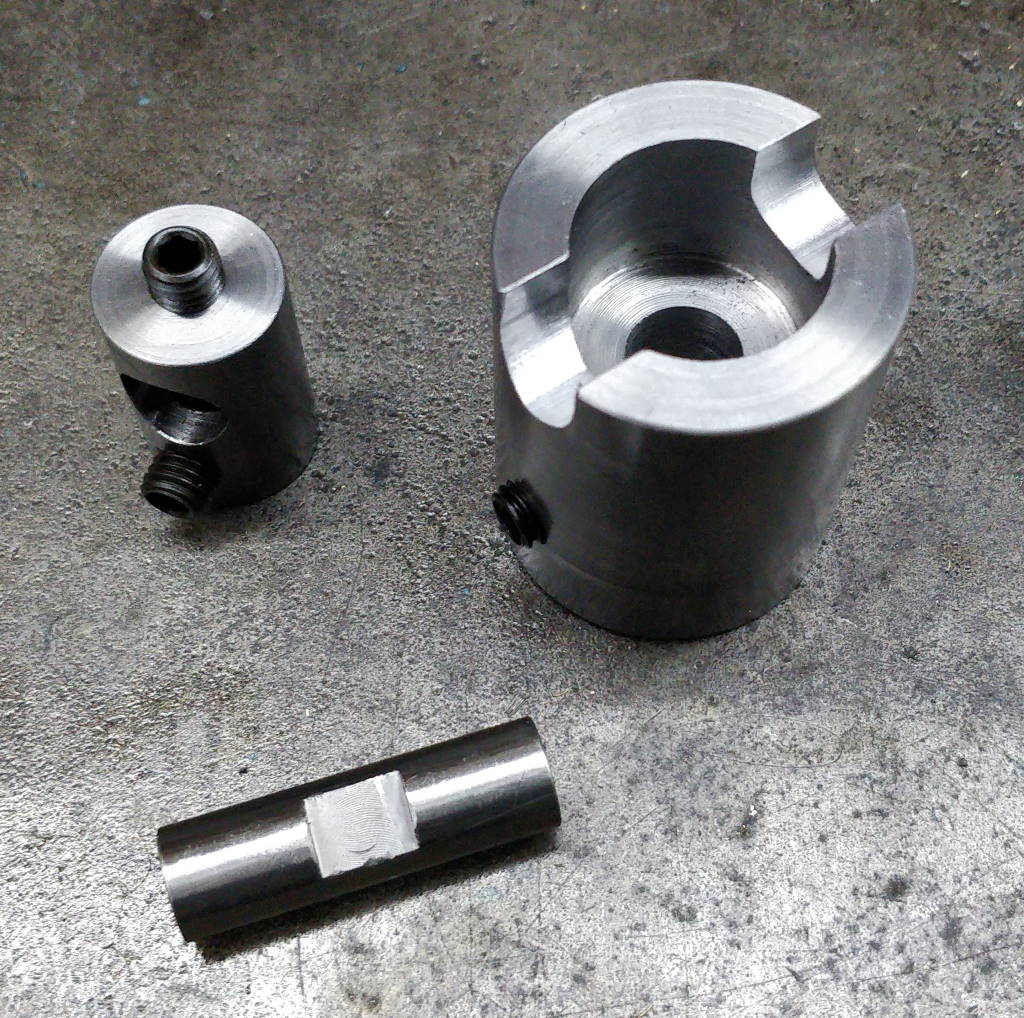
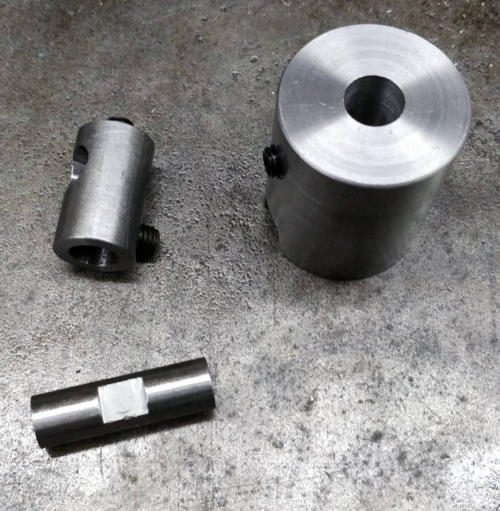
This photo shows the basic parts that make up the coupling. The cross bar is made out of a short
off-cut of 12 mm silver steel; the other components are EN1A. The large body attaches to
the end of the leadscrew with the grub screw in the side; the smaller body attaches to the hand
wheel shaft with its own grub screw and has a grub screw in the end to hold the cross-bar in place.
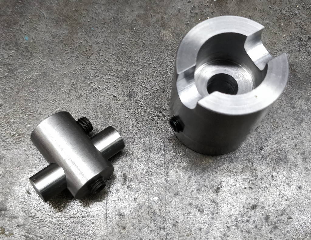
This photo shows the assembled parts.
Hand Wheel
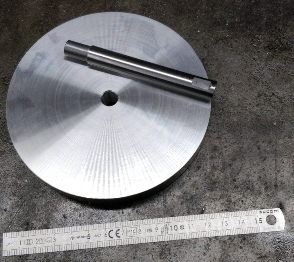
The hand wheel is made from a 125 mm disc of aluminium; its shaft is made from 12 mm silver steel. A short section of the shaft is turned down to 10.032 mm; the hand wheel was faced on one side and a 10 mm hole was drilled and reamed in the centre.
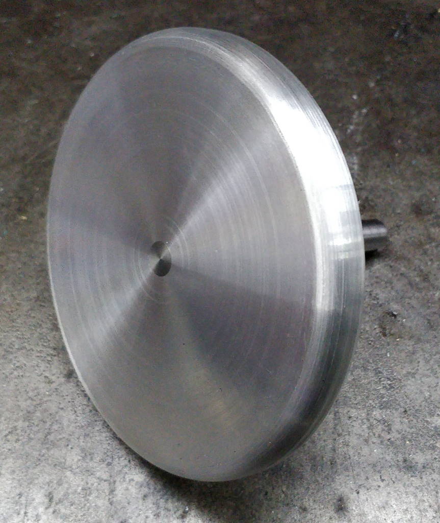
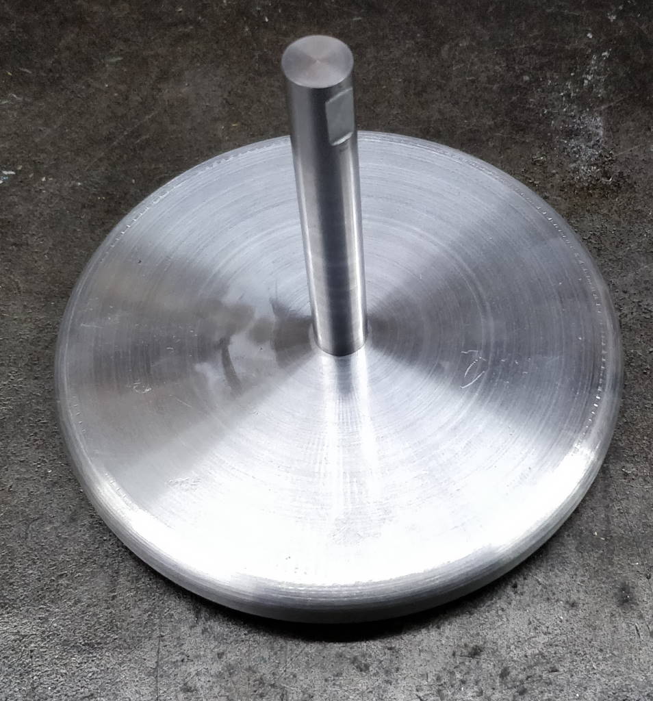
The hand wheel was put in the domestic oven (on maximum temperature, about 230°C) and the shaft was put in the freezer. Once the hand wheel was up to temperature, the two parts were brought together and the shaft was quickly tapped into place with a soft hammer. Once the parts were back at room temperature, the shaft was mounted in a collet chuck on the lathe and the outer surface of the hand wheel was faced. A corner rounding end mill was then used to put a radius on both edges of the wheel (for one edge the lathe was run in reverse due to the shape of the corner rounding end mill). The profile was then touched up with a file while the lathe was turning.
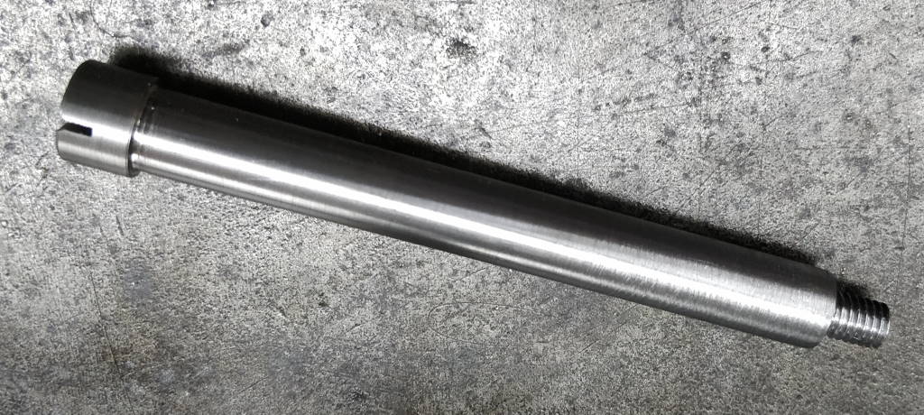
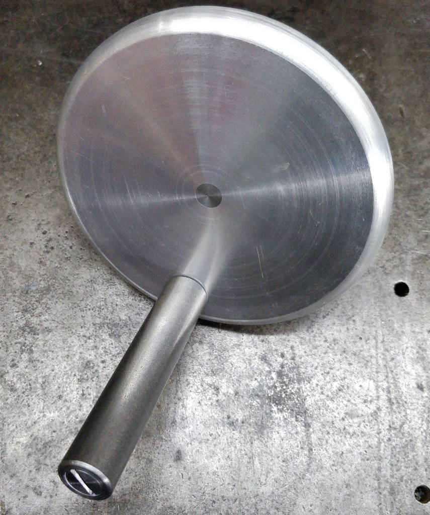
A shoulder screw was made out of a length of EN1A. This fits into an EN1A handle and allows the handle to rotate freely while being held firmly to the hand wheel by a blind M8 tapped hole.
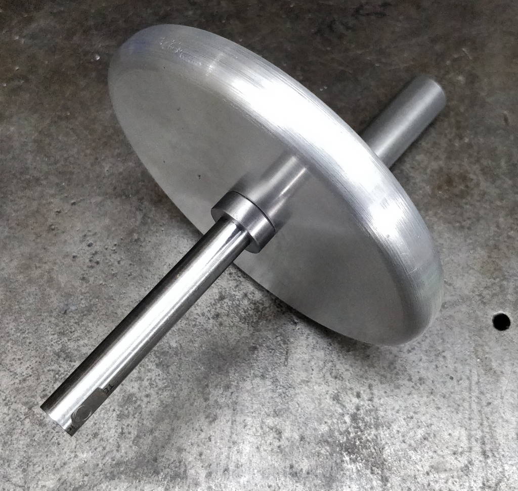
A small washer was turned to separate the face of the hand wheel from the bushing in which the shaft runs; the washer is a loose fit on the shaft.
Frame
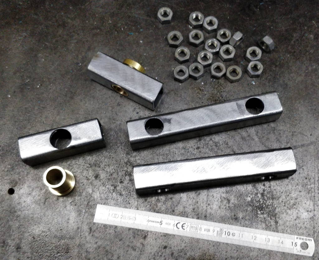
The frame (shown assembled at the top of this page) is made from 20 mm × 20 mm × 2 mm box section steel. The nuts you can see in the top of this photo were BZP nuts that had been soaked in hot citric acid solution to remove the zinc plating.
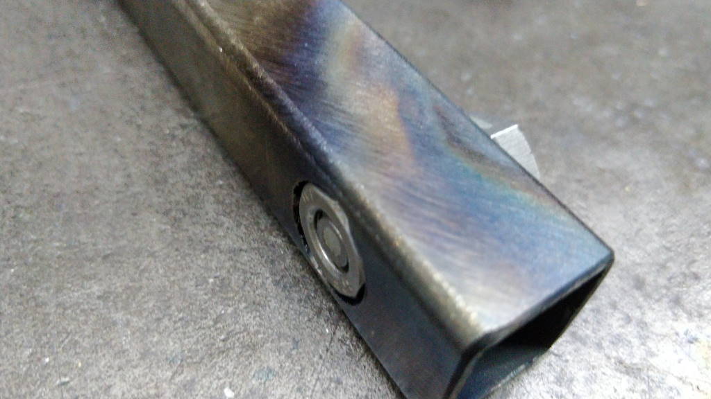
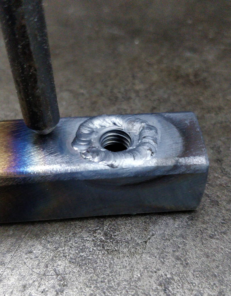
The nuts were welded into the box section (one on each side to provide more thread engagement) to provide mounting points. A screw (again with the zinc plating removed) was used to ensure the threads of the two nuts were in sync with one another.
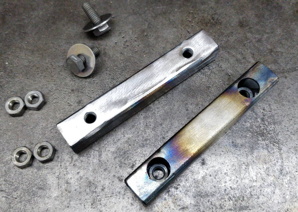
This photo shows the frame arms after the first two nuts had been welded in place and the welds cleaned to allow flush fitting of other components.
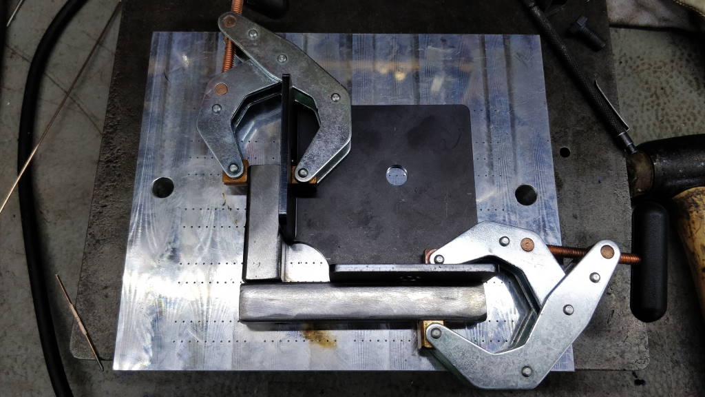
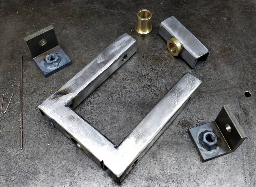
The frame was TIG welded together using a simple right-angle jig. As you can see in the right-hand photo, I also welded some nuts to the inside surface of two angle mounting brackets.
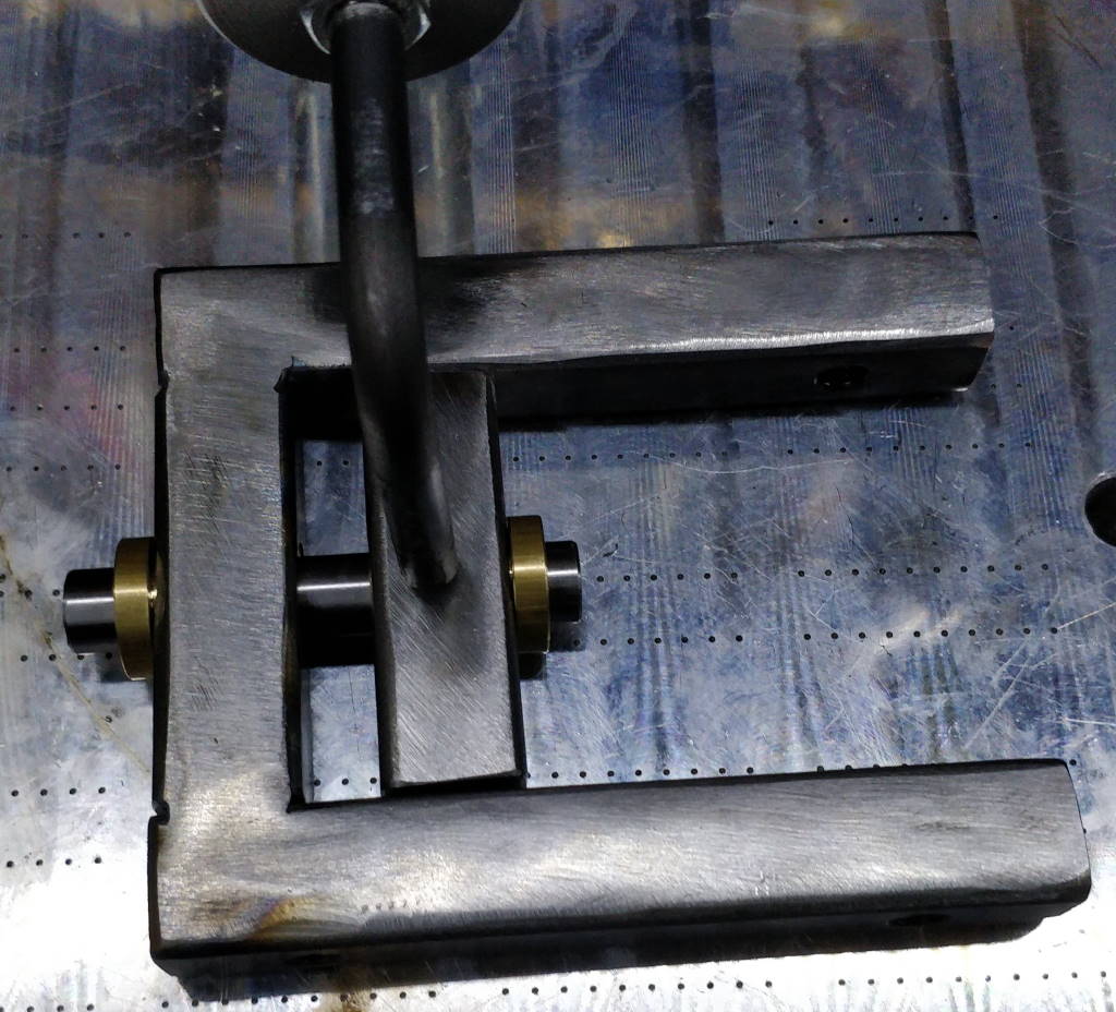
To weld the cross beam, the two bushings (machined from brass bar as I didn't have any bronze in the right size) were installed and an off-cut of silver steel was inserted to keep them in alignment. The cross beam was then welded and the welds cleaned.
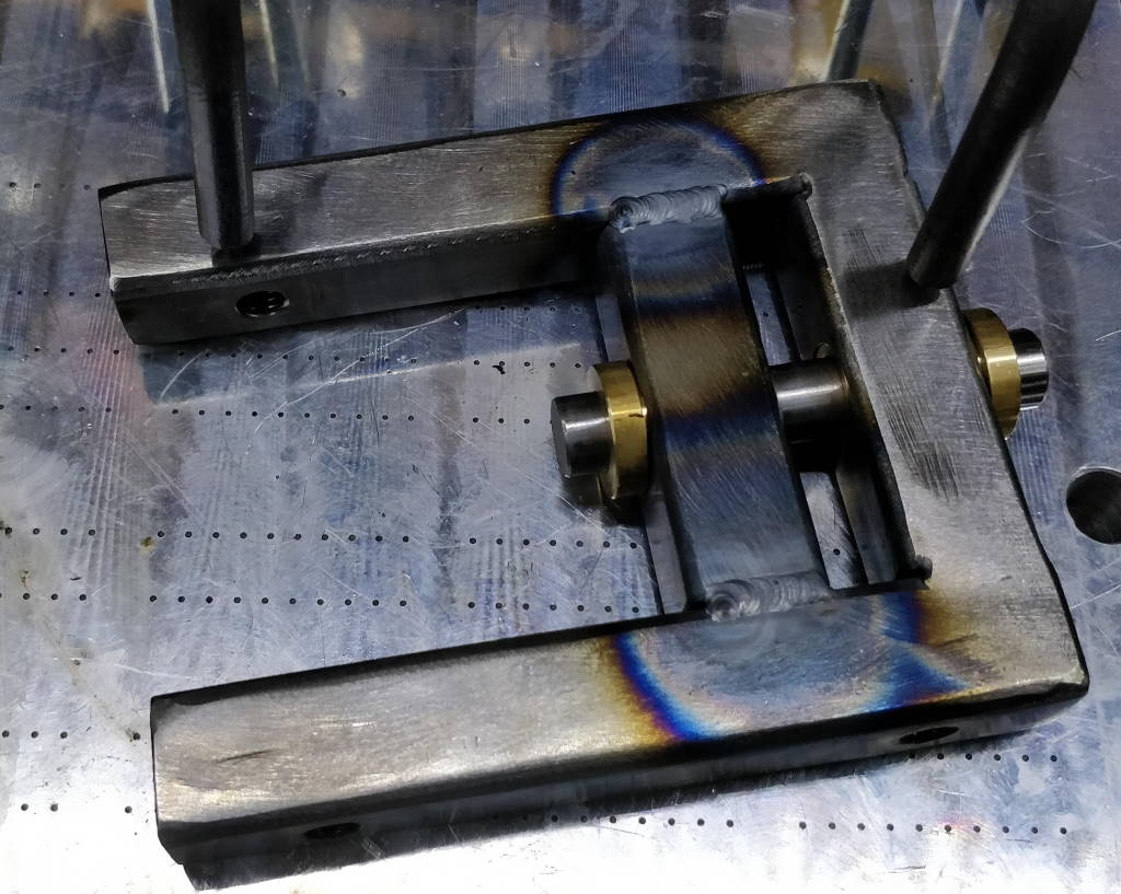
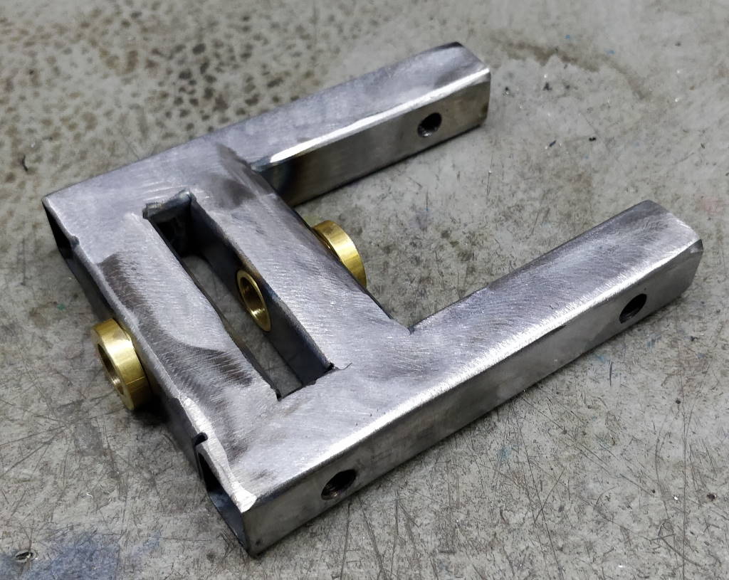
These photos show the finished frame before and after cleaning the welds with a flap disc on an angle grinder.
Mounting Brackets
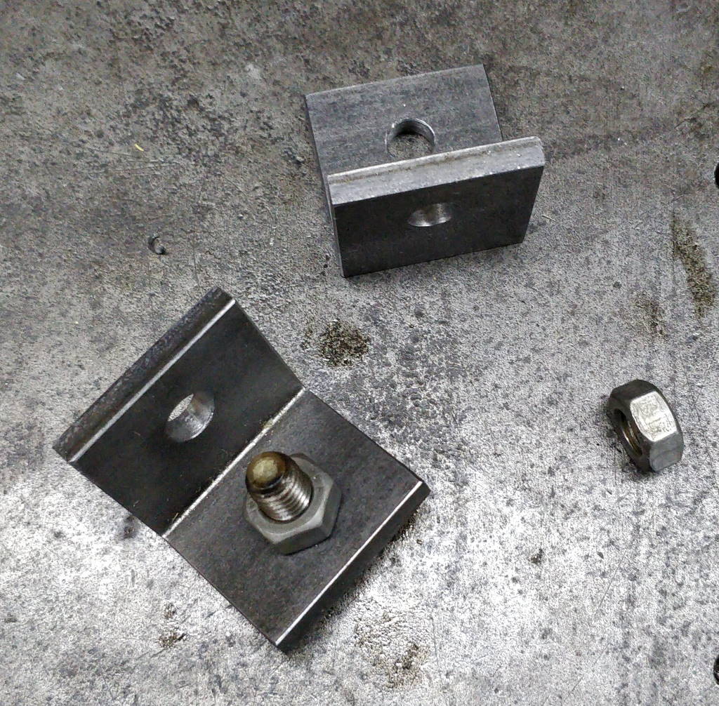
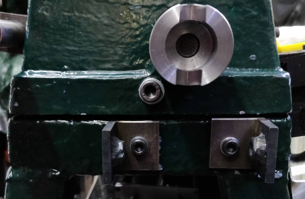
These photo show the two angle brackets that are used to mount the vice handle frame. The nuts were welded in place (shown in an earlier photo) to simplify mounting. The brackets are attached to the base frame of the bandsaw using a couple of M8 tapped holes.
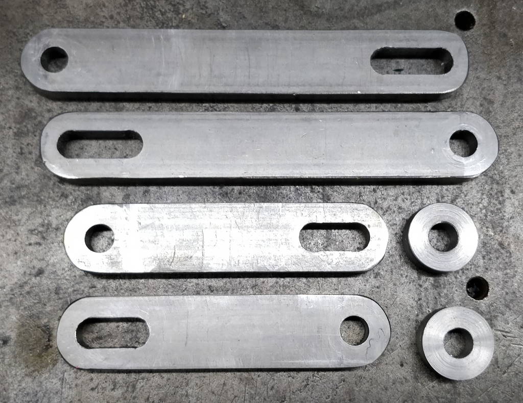
These components are the uprights for the vice handle frame and are used to attached the top frame to the brackets. The uprights are made from 8 mm × 20 mm EN3B. They are arguably unnecessarily thick for the purpose, but I had a lot of steel in this size and it seemed sensible to use it rather than buying more for the purpose. The spacers you can see in the bottom right of the photo are EN1A, 20 mm diameter and 8 mm thick with a 8 mm hole through the middle.
Assembly
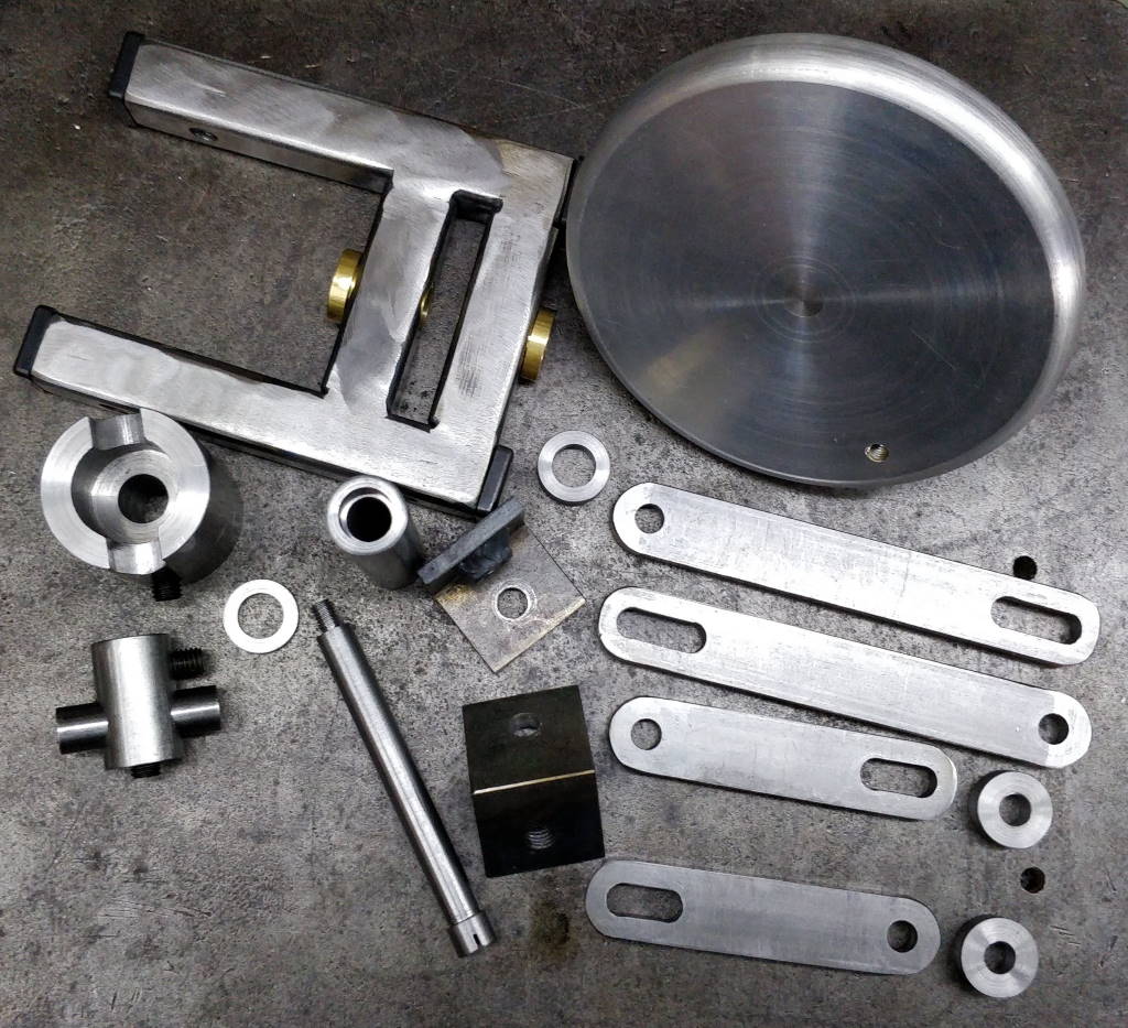
This photo shows all of the parts of the vice handle frame together in one photo.
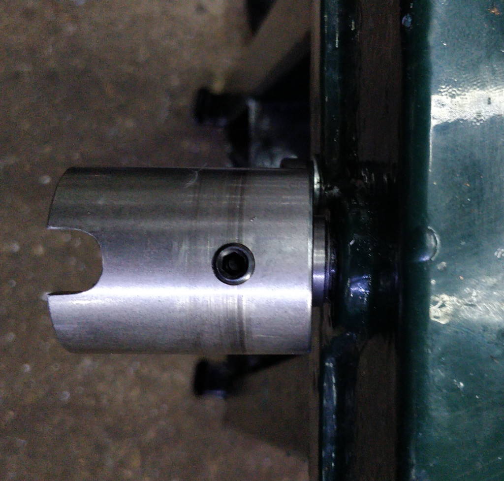
First, the coupler is fitted with a small washer to keep it away from the angled face of the lower casting.
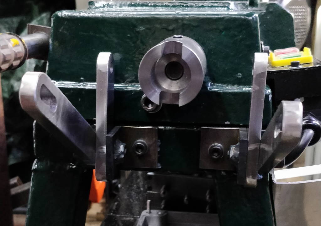
The mounting brackets and uprights are then fitted in approximately the right place.

The upper frame and hand wheel are then fitted. It is then "just" a process of tweaking all the screw positions until the vice handle turns freely over the range of travel of the moving jaw of the vice. This took quite a long time but I got there in the end!
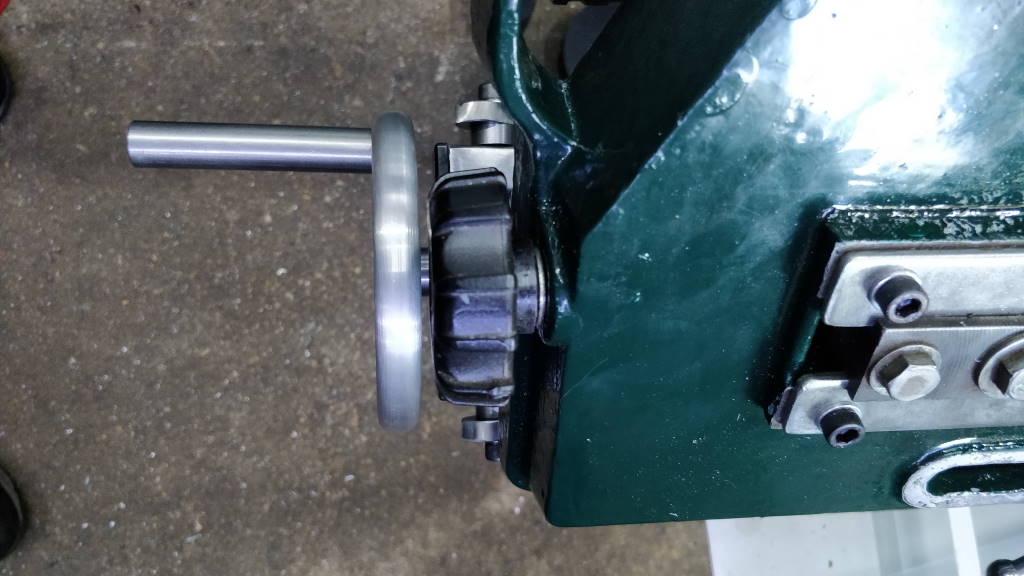
This photo shows the hand wheel position when the upper arm of the bandsaw is down. It can be easily accessed without any interference with the upper arm.
This website is free and ad-free, but costs me money to run. If you'd like to support this site, please consider making a small donation or sending me a message to let me know what you liked or found useful.
