Bandsaw Cut-Off Table
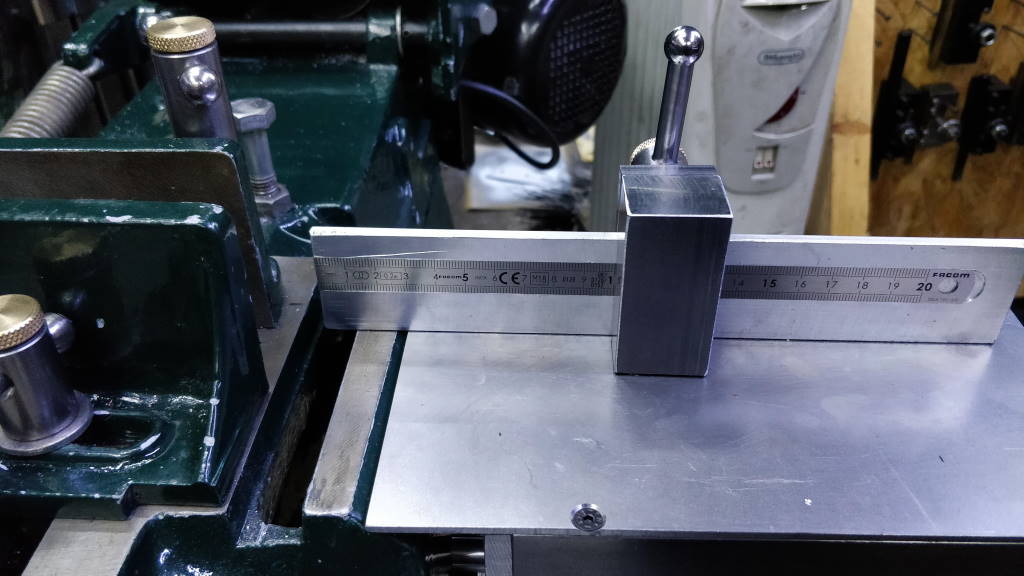
This design is loosely based on an idea by Dr Mike Cox. The primary purpose of the cut-off table is to support the piece being cut and catch the cut-off piece rather than allow it to roll into the swarf tray or across the floor and underneath something. Like Mike's mark 2 version, mine also includes a length stop that helps when cutting multiple pieces of bar stock to the same length.
The cut-off table is designed to allow stock up to 200 mm long to be cut to accurate lengths. It is also designed to be removed and refitted very quickly. Due to the limited space in my workshop, the cut-off table protrudes into an area where I walk and would get in the way. Making it quick to fit and remove makes it much more likely that it will get used but allows it to be out of the way when not required.
Casting Modifications
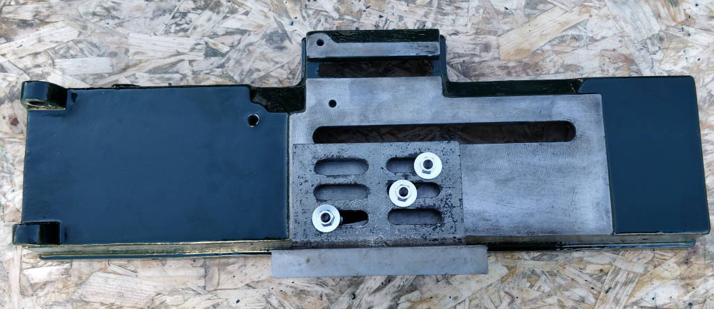
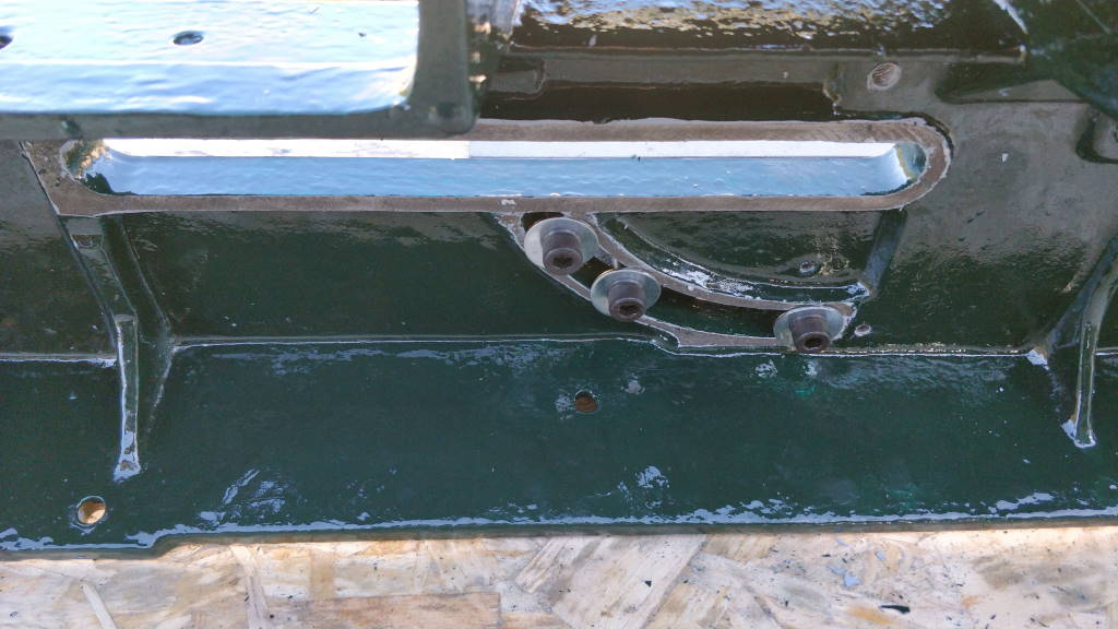
While I was in the process of restoring the bandsaw and the castings had been separated from the rest of the saw, I made some relatively simple modifications to the lower casting to make it easy to mount the cut-off table. The photos above show an angle plate that I mounted to the lower casting using the slot for the fixed vice jaw.
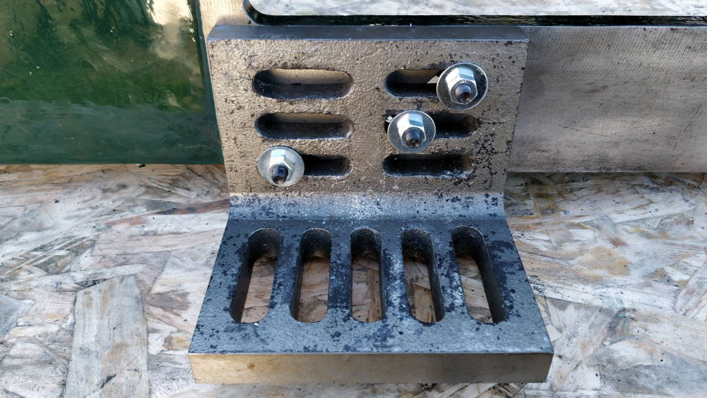
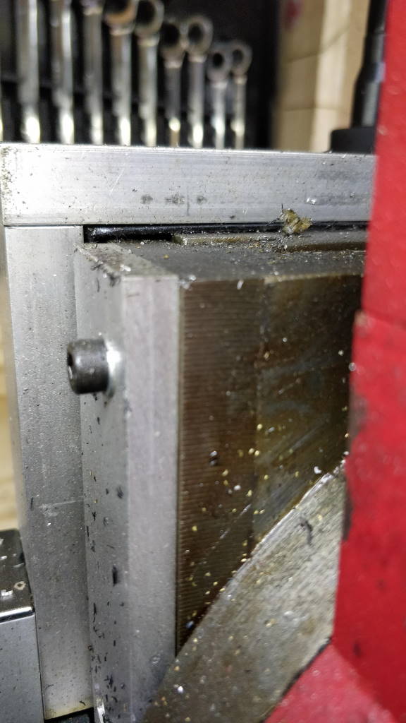
This photo shows a close up of how the angle plate is mounted to the casting.
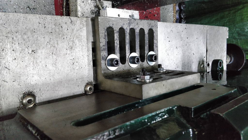
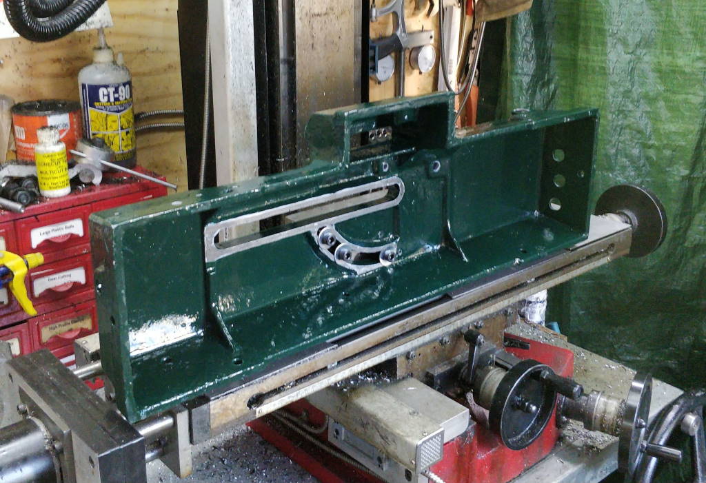
The casting was mounted onto the table of the milling machine using the angle plate. This was very much stretching the limits of my little bench top mill! Like all photos on this website, you can click on the images for a better view. The casting was "clocked" true to the X and Z axes. For the X axis, a dial indicator was run along the machined surface on the top of the casting (the one that the angle plate is clamped to). For the Z axis, an indicator was run along the inside of the slot for the moving vice jaw.
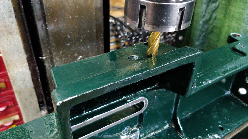
The first operation was to mill some flat surfaces in five places on the side of the casting. The face that is being milled has a significant draft angle and I wanted to create a reference plane that is perpendicular to the machined top face of the lower casting (on which the material to be cut sits). I used an edge finder to zero the DRO's Y axis at the machined surface (so that I could make the mounting points be at a defined location relative to that surface).
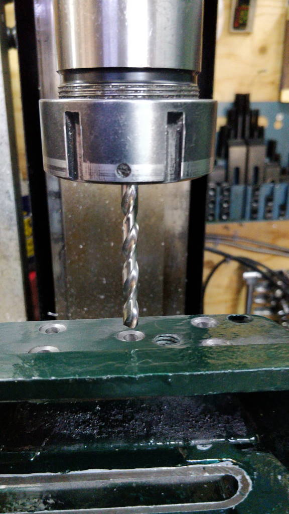
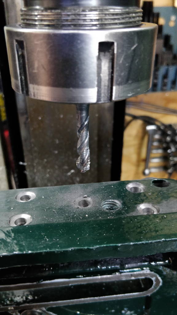
I then spot drilled and drilled five holes through the casting in the centre of the machined areas. I held the drill bit in a collet chuck rather than a drill chuck as the drill chuck I've got is significantly longer than the collet chuck. As you can see from the right-hand photo (which shows the top of the Z axis slide), this was right at the upper limit of travel of the Z axis and (as you can see in the left-hand photo) there was only just enough room to fit the drill bit.
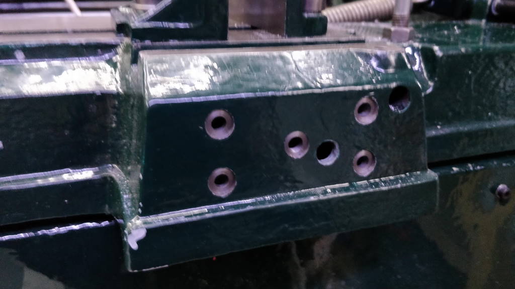
The four outer holes were reamed to 6 mm: these features provide the alignment for the cut-off table. The middle hole was tapped M8.
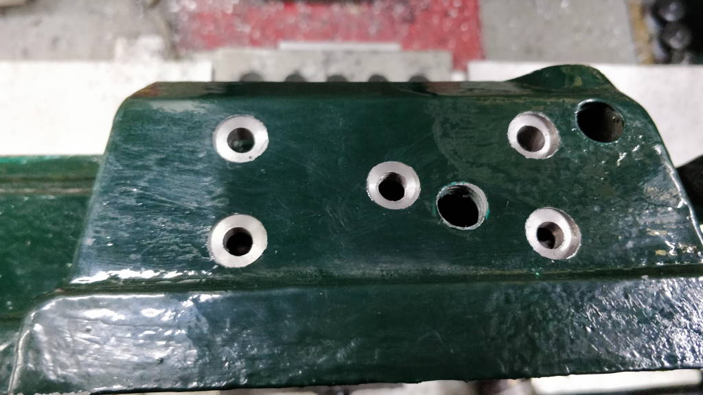
This photo shows the finished mounting features machined into the casting. The other (M12 tapped) hole that you can see in the photo was an old feature that I had previously hand drilled and tapped into the casting for an earlier (and much cruder) length stop. This hole is no longer used.
Due to the draft angle on the casting, the machined surface of the five holes are at different heights to one another. The top holes are 3.5 mm deeper than the bottom holes; the middle hole is half-way in between.
Cut Off Table Parts
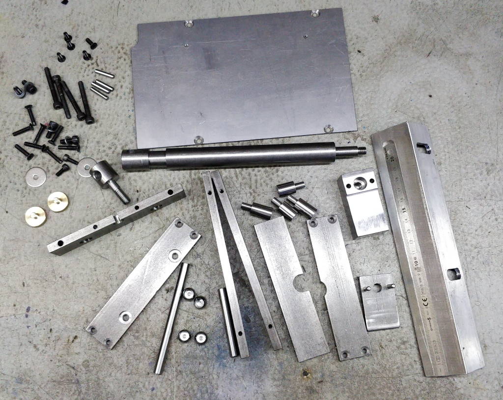
This photo shows all of the parts that make up the cut-off table. The fasteners are a mix of M4 and M5; the dowel pins are 4 mm and the circular components near the bottom of the photo are 12 mm unhardened steel balls that have an 8 mm hole drilled into them.
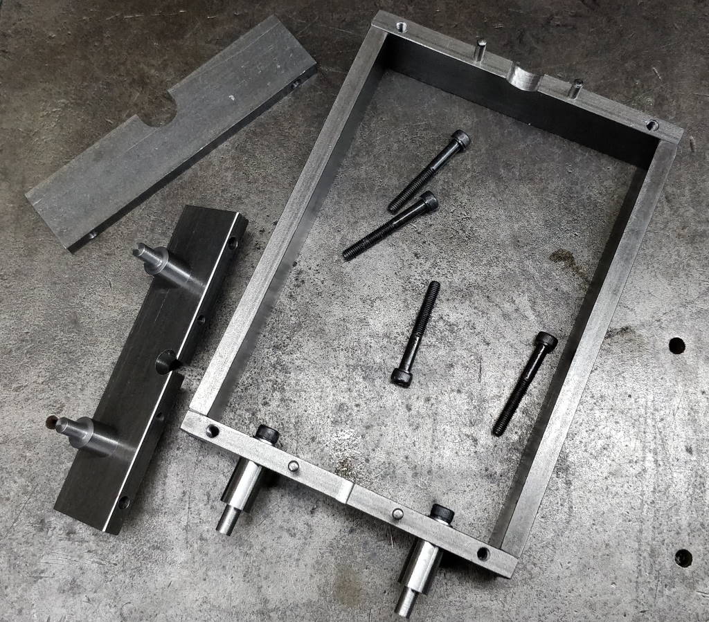
This photo shows the first few parts of the cut-off table having been assembled. The frame is made from 8 mm × 30 mm EN3B flat bar. The shorter lengths are 130 mm long, the longer ones are 172 mm long. The frame that has been assembled in this photo is held together with M4 countersunk screws. The dowel pins provide alignment between the frame as assembled in this photo and the lower support pieces that are shown on the left-hand side of the photo.
The pins are machined from 12 mm silver steel. The outer ends of the pins are turned down to 6 mm to be a close sliding fit in the reamed holes in the casting. On the other end of the pins there is an M5 tapped hole to hold them to the frame. The body of the lower pins is 3.5 mm shorter than that of the upper pins to account for the taper of the casting. The pins sit in some machined pockets in the frame (set at the same depth to ensure that the frame is perpendicular to the top surface of the casting.
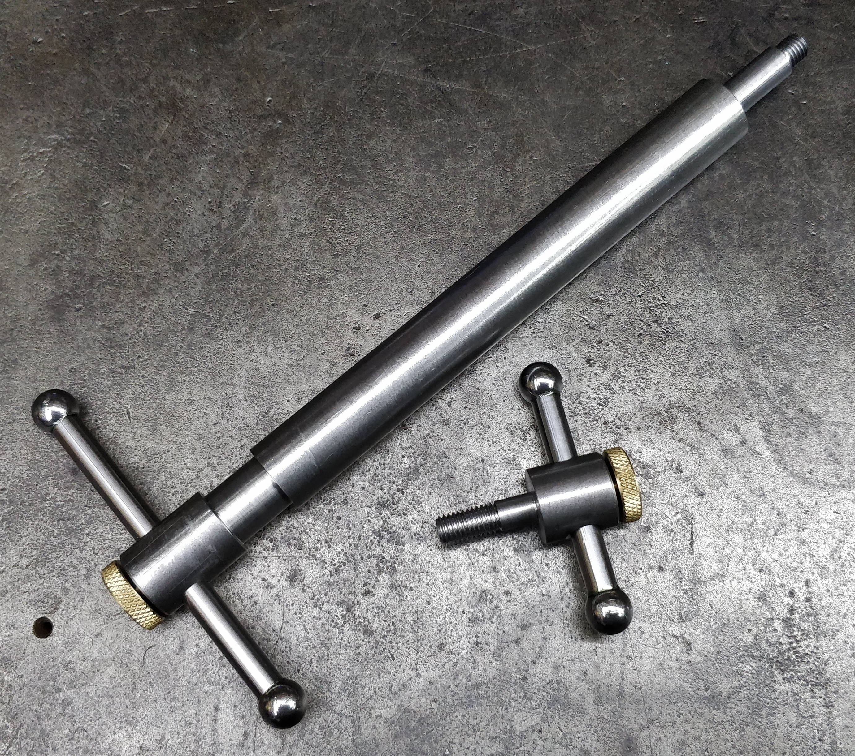
This photo shows the two custom made screws that are used in the assembly. The body of the screws is made from 20 mm EN8. The tommy bars are 8 mm silver steel with 12 mm steel balls held on the end with Loctite 603. The knurled brass screws in the end of the main screws are used to lock the tommy bars at a particular position and stop them rattling around.
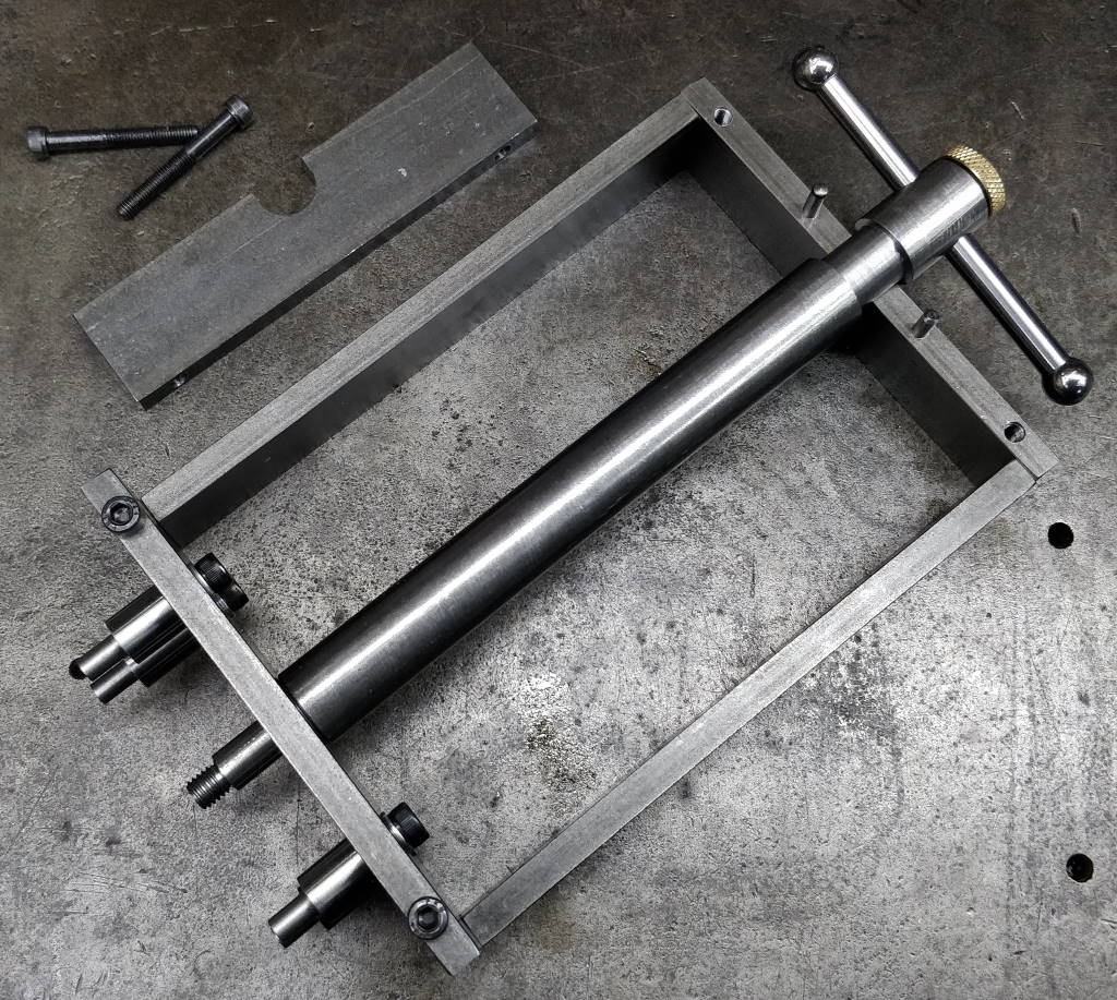
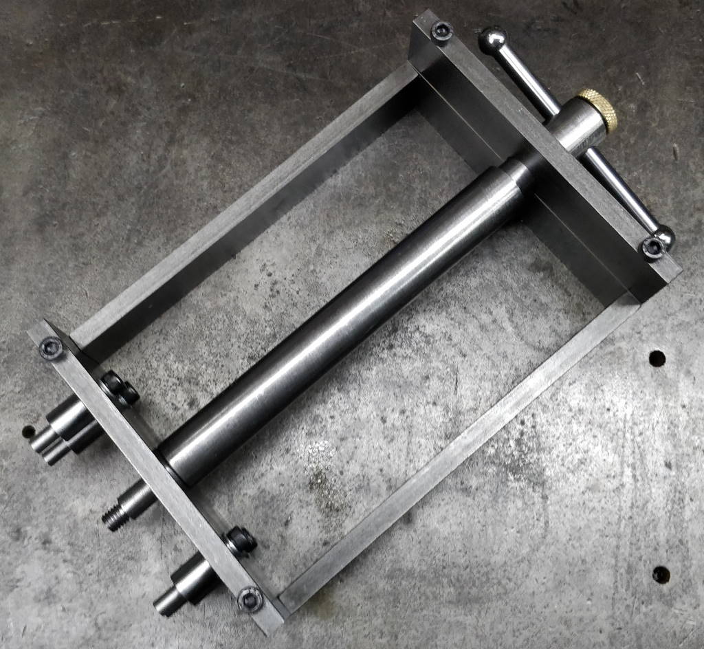
The main frame screw fits into holes that are drilled in the gap between the upper and lower frame parts. On the side closest to the bandsaw body, the hole is a simple hole that the screw slots into. The hole in the outer end was initially drilled and bored to 16 mm diameter with the two frame parts clamped together and then the lower frame piece (shown separated in the left-hand photo above) had the slot opened out so that the frame piece can be fitted over the screw, while still supporting the outer end of the screw and keeping it captive.
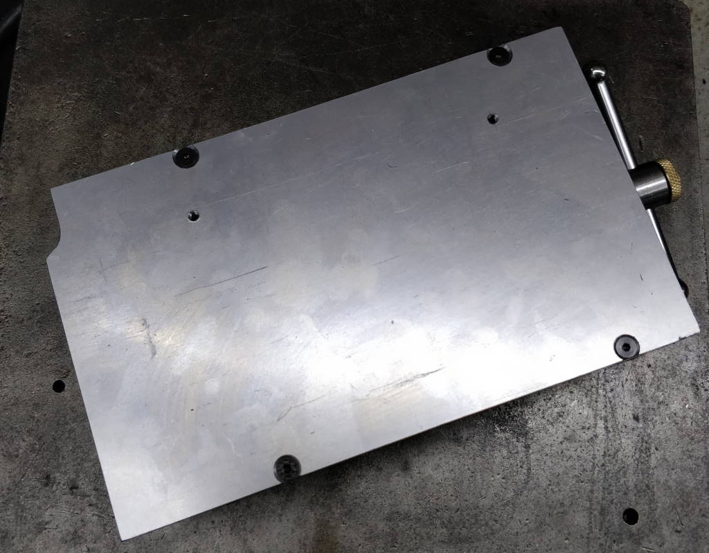
The side bars of the frame have M4 tapped holes drilled in the top surface. The top plate is cut from a piece of 3 mm mild steel plate. It has four countersunk holes to mount to the frame and a cut out for the bulge in the casting.
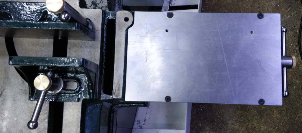
The table frame fits very easily to the bandsaw casting using the features described previously and shown in the left-hand photo. The four pins slot into the four outer holes in the casting and then a few turns of the screw locks it in place. The tommy bar hole in the screw has been drilled at an angle that results in the screw locking with the tommy bar in the horizontal position, out of the way of any bar stock in the bandsaw vice.
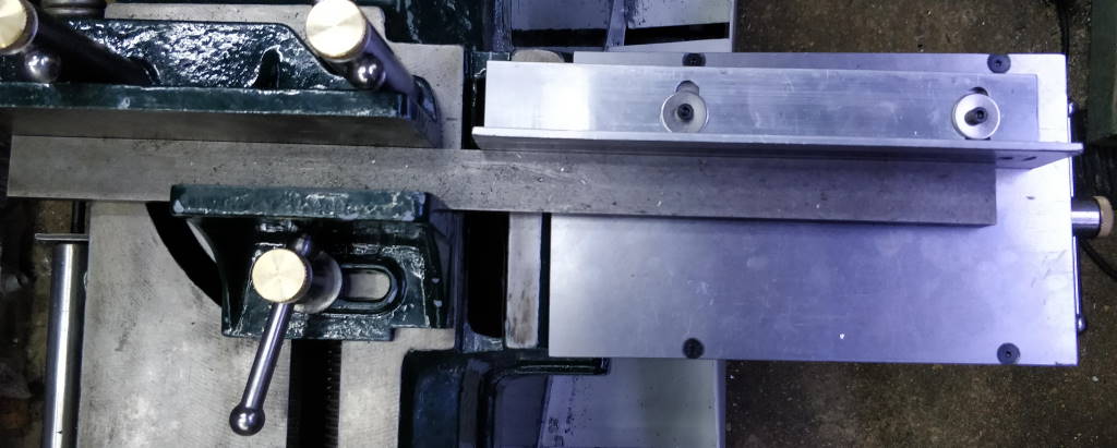
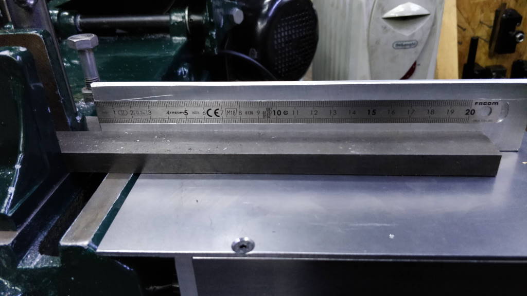
The photos above show the fence that is fitted to the cut-off table. It is made from a length of 40 mm × 40 mm × 5 mm angle aluminium. The fence is mounted using some slotted holes to allow it to be adjusted to be inline with the fixed vice jaw (which may change in position if the blade is adjusted). A slot has been milled in the fence for a Facom DELA.1051.200 metric-only 200 mm long steel ruler. The original intention had been to fix the ruler in with some form of adhesive, but after milling the slot it was found that the ruler was a very good tight fit and did not need any additional retention. As you can see in the right-hand photo, I decided to set the ruler relatively high up on the fence. This means it can't be used for direct reading on small stock, but makes it a lot easier for me to see (I'm very tall). If I find it problematic over time, I may add another slot and install a second ruler. When used with the length stop, the position of the ruler is not critical anyway.
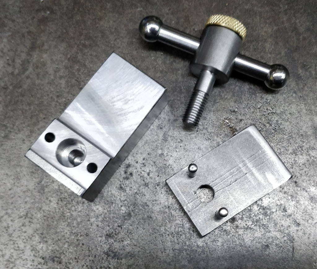
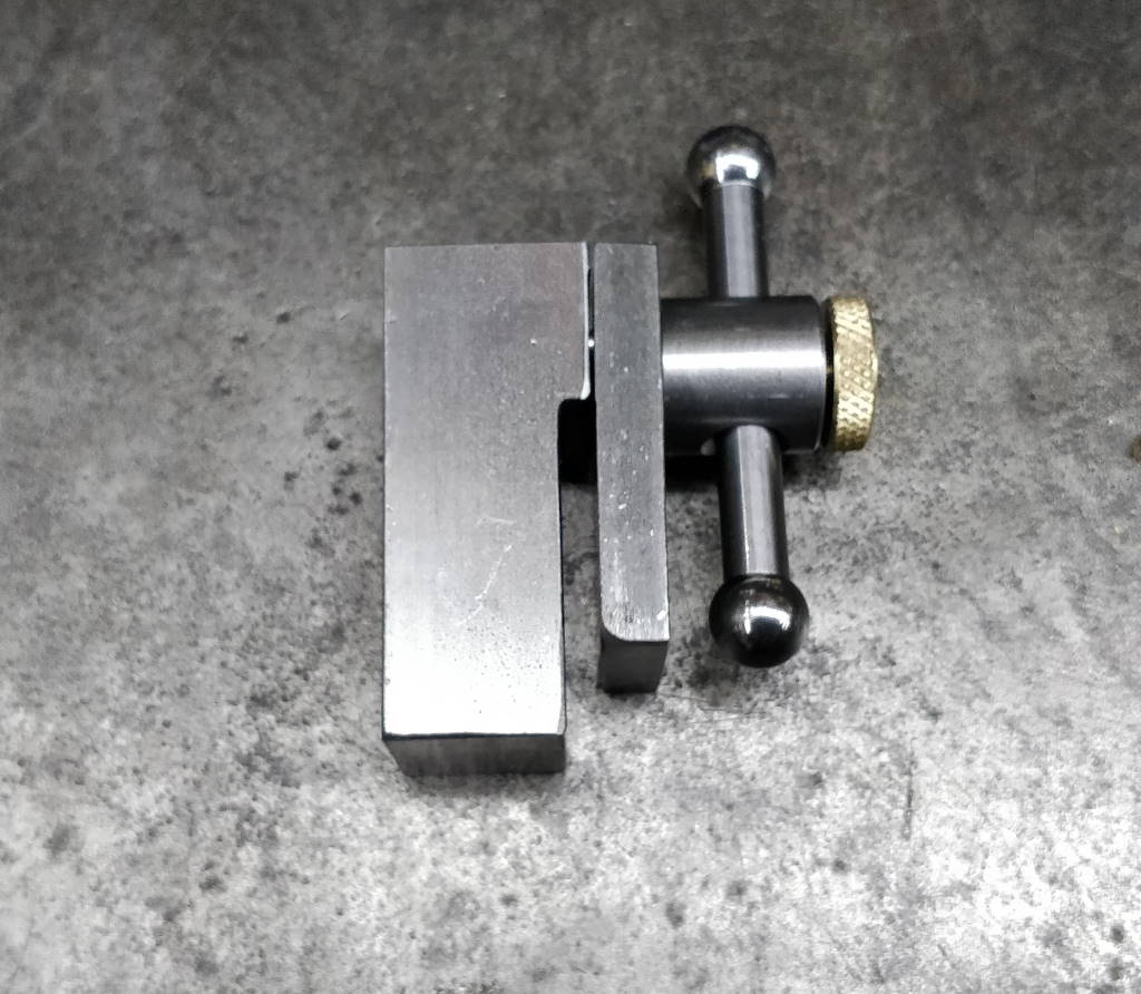
These photos show the length stop. It is a very simple design with a clamping mechanism modelled on a milling machine table clamp. The small step you can see in the bottom-left of the left-hand photo acts as the pivot point and the screw pulls the clamp tightly onto the aluminium angle. The dowel pins are there to stop the two halves of the clamp from rotating relative to one another.
The deep counterbore in the larger piece was drilled in case I felt it would be a good idea to add a spring to pull the two pieces apart when the screw was loosened. I have not found this to be necessary so haven't fitted the spring.
Dr Mike Cox's version of the length stop reaches across the whole length of the cut-off table. I decided this was unnecessary as there would always be one part of the piece to be cut that would be in contact with the fixed jaw of the vice. This would not apply if the end to be cut had an angled end where for some reason the longer end had to be on the moving jaw side, but I felt that this would be a very rare occurrence and wasn't worth worrying about.
The photo at the top of the page shows the length stop in place on the cut-off table.
This website is free and ad-free, but costs me money to run. If you'd like to support this site, please consider making a small donation or sending me a message to let me know what you liked or found useful.
