Bandsaw Restoration: Assembly
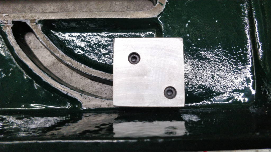
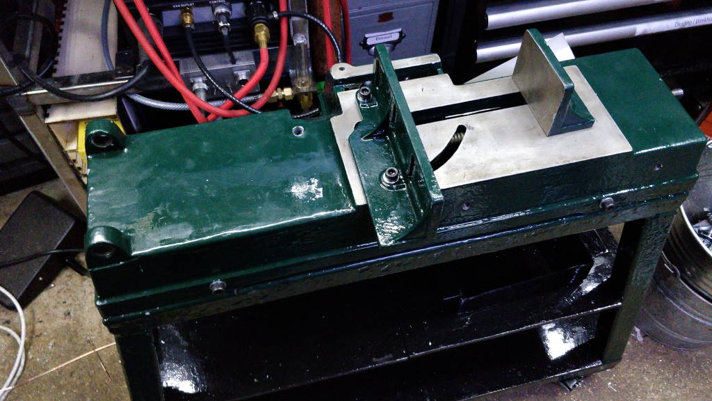
The t-nut saver was fitted to the underside of the bottom casting. The vice jaws were then attached with cap screws (to ensure the vice screw and the t-nut stayed in place) and then the casting was attached to the base frame.
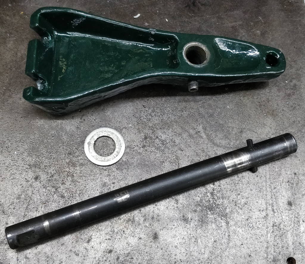
This photo shows the painted hinge bracket and the hinge bar on which it mounts. The roll pin has been replaced with a new one (just because I couldn't see a reason not to).


These photo show the hinge bar as it was fitted. As you can see in the left-hand photo, I applied some white lithium grease to the area where the hinge bar would be inserted in the base casting.
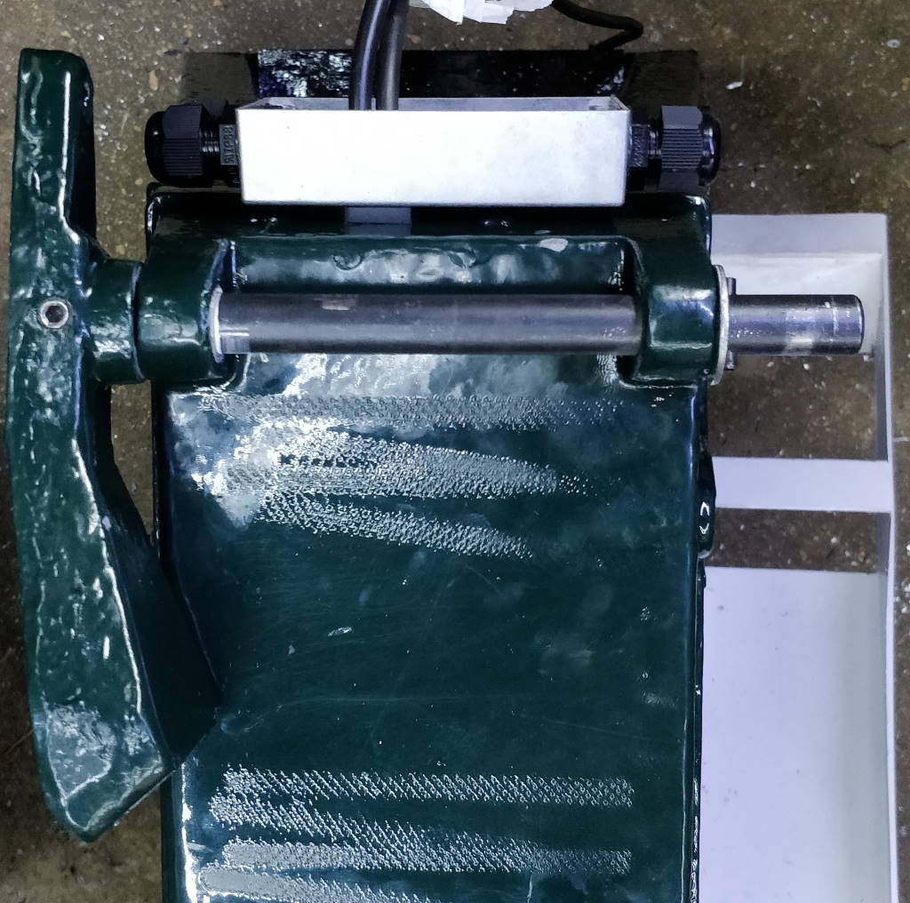
This photo shows the hinge bracket fitted onto the bar. It also shows an effect of my lack of experience in painting. I had applied the paint in the thickness that it came out of the can rather than trying to thin it before painting. As a result, the paint went on very thickly and probably hadn't fully dried despite it being several weeks earlier. I then decided to rest the motor on the base casting to keep it out of the way, using some "elephant bog roll" (blue paper roll) to "protect" the paint. The effect of the weight of the motor was to imprint the pattern from the paper roll on the paint. You can see where I've obviously shuffled the motor into a few different places. Ah well, live and learn... I'll probably touch up the paint in this and a few other areas once the weather is warmer and the paint stands more of a chance of drying quickly.
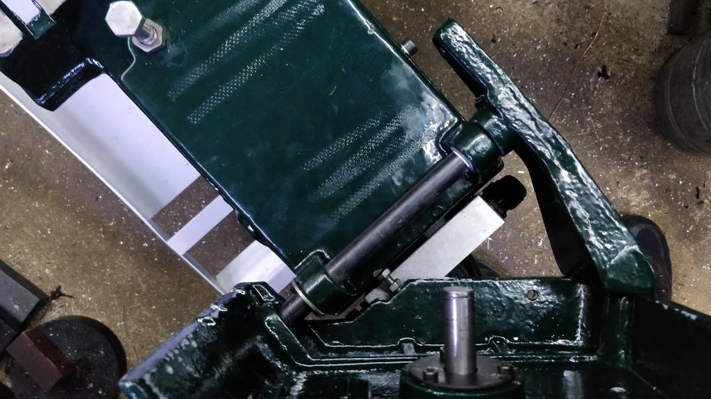
This photo shows the upper casting fitted to the hinge. At this point I realised that it is impossible to fit the drive wheel onto the lower shaft when the casting is mounted on the hinge, so I had to take it back off again!
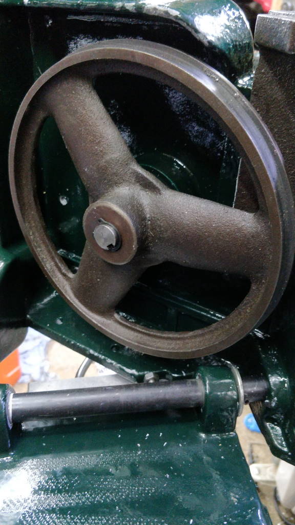
The drive wheel fits on very easily (with the top casting removed). It is driven with a key and held in place with a circlip as you can see in this photo.
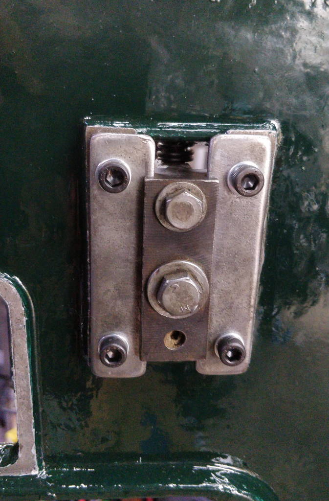
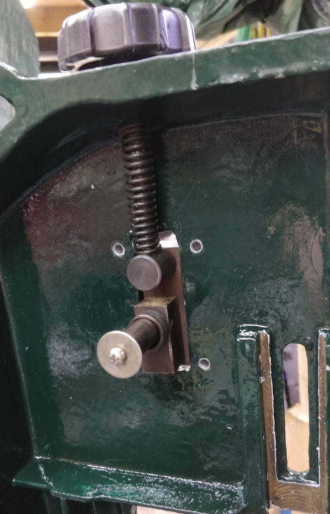
These photos show the bracket that holds the idler wheel in place. I decided against dismantling the sliding idler bracket during the restoration and therefore it was simple to refit it. The only modification I made was replacing the slide plate mounting screws with cap screws.
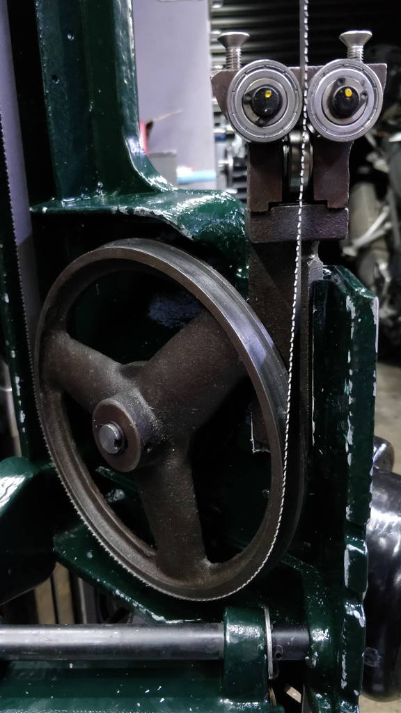
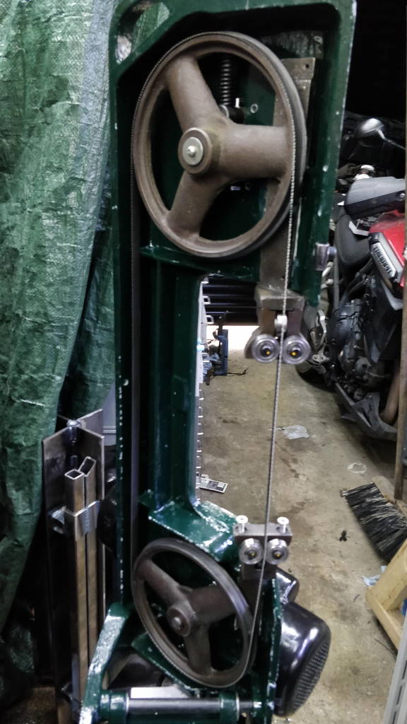
These photos show the wheels and blade fitted to the bandsaw and the blade guide bearings having been adjusted.
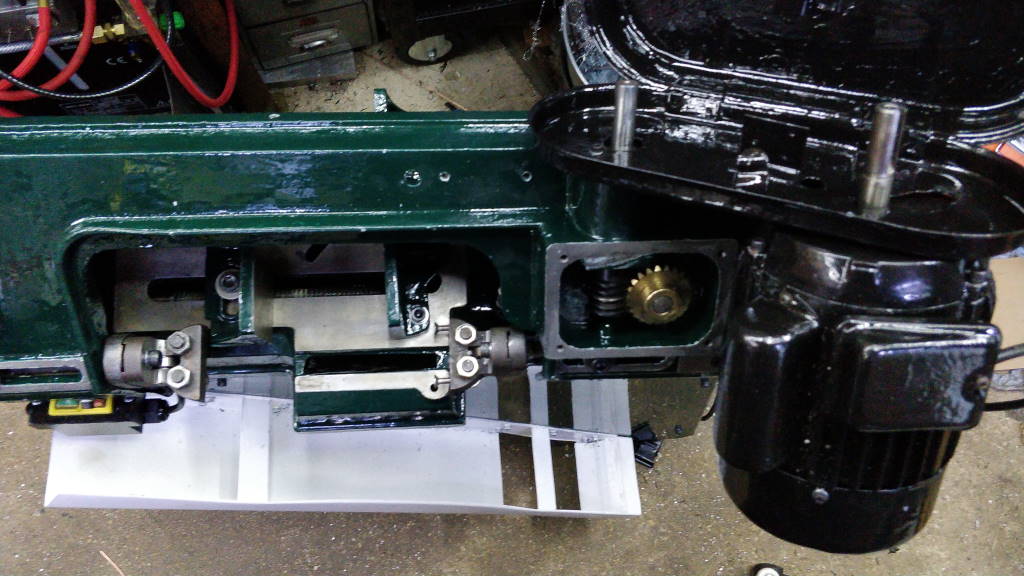
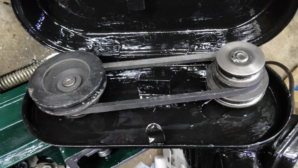
These photos shows the initial fit of the motor and the belt cover and in the right-hand photo the pulleys and belt. I attached a small piece of self-adhesive felt to the top of the motor to stop the belt cover from vibrating noisily against the motor.
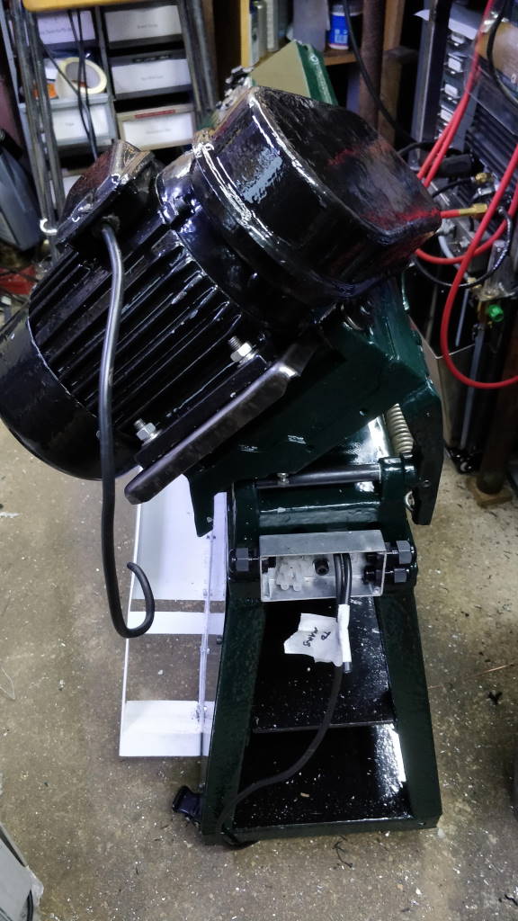
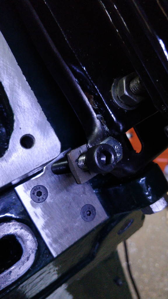
These photos show another two views of the motor. On the right-hand photo you can see the simple modification that I made to the hinge mechanism. The small steel plate has two tapped holes. One is used to attach it to the original hinge screw hole (which has been drilled out); the other is used for a new hinge screw. The advantage of this plate is that it moves the hinge screw out from underneath the motor and makes it possible to use a hex key instead of a spanner.
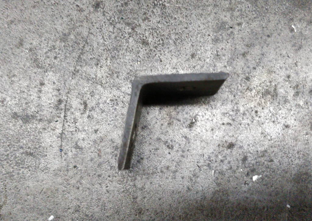
This photo shows one of the brackets for the spring tensioner arm in the condition it was in when I removed it from the saw. To bend it back to 90°, I used the bench vice and a hammer.

This photo shows the spring arm and spring fitted. As you can see, the vice jaws are still held in place with cap screws; this is rectified in the next section.
This website is free and ad-free, but costs me money to run. If you'd like to support this site, please consider making a small donation or sending me a message to let me know what you liked or found useful.
