An Over-Engineered Boat Vice
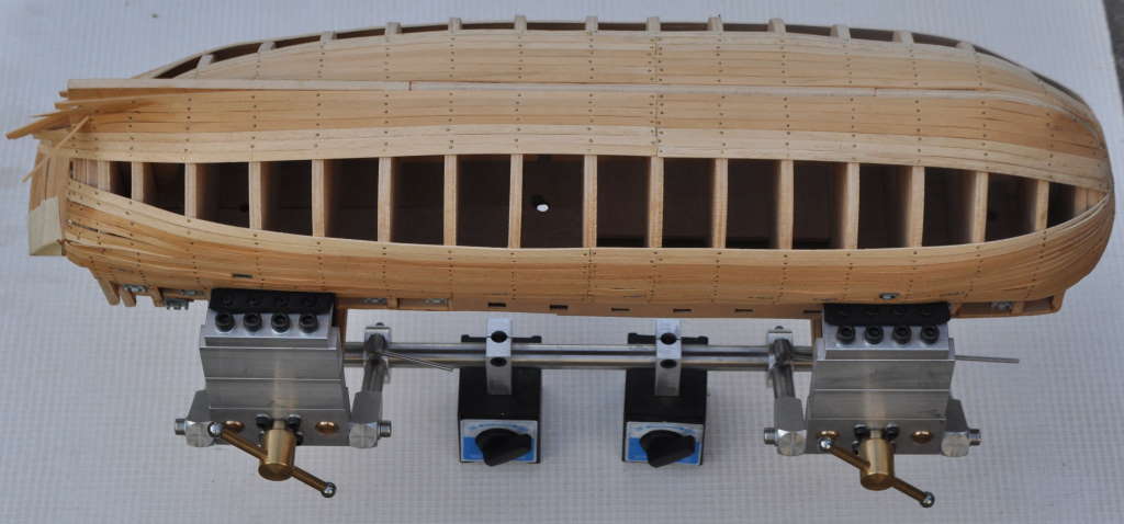
This is probably one of the most ridiculous and unnecessary projects I've ever done, but it was quite fun, so what the hell. As the title suggests, it's a vice for holding onto a boat model (a model of the HMS Victory) I've been making on-and-off (mostly off) for the last 10 years. I'd seen some designs for vices for holding model boats by the keel, but my model doesn't have a keel yet (and I'm not sure the one it'll eventually get will be strong enough). As much as anything, I made this vice to experiment with a few different machining techniques and ideas and because I had some material lying around that I wasn't sure what else to do with!
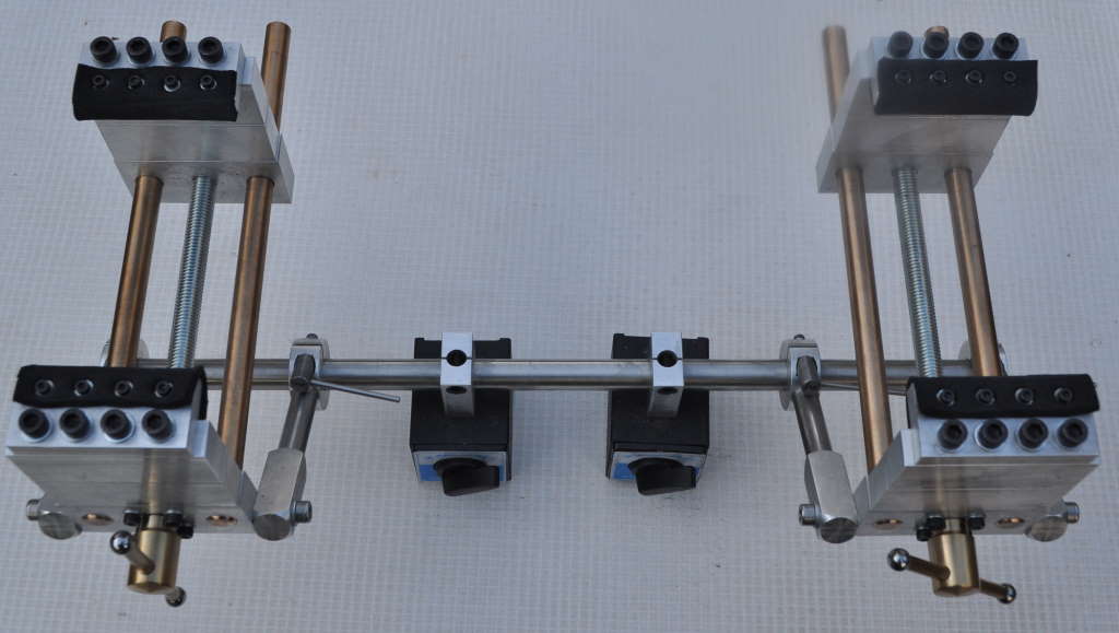
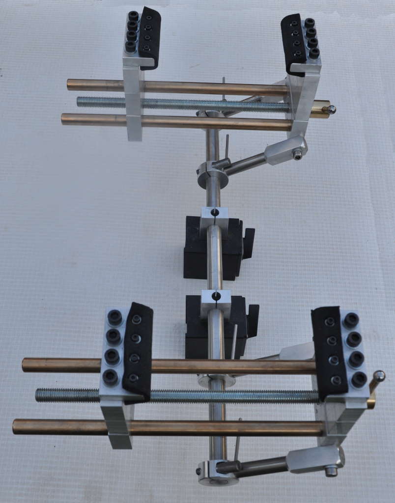
The vice is made out of a mixture of materials, a lot of which came out of the skip at my work. The bar that runs along the bottom of the vice is 16 mm 303 stainless steel, about 450 mm long.
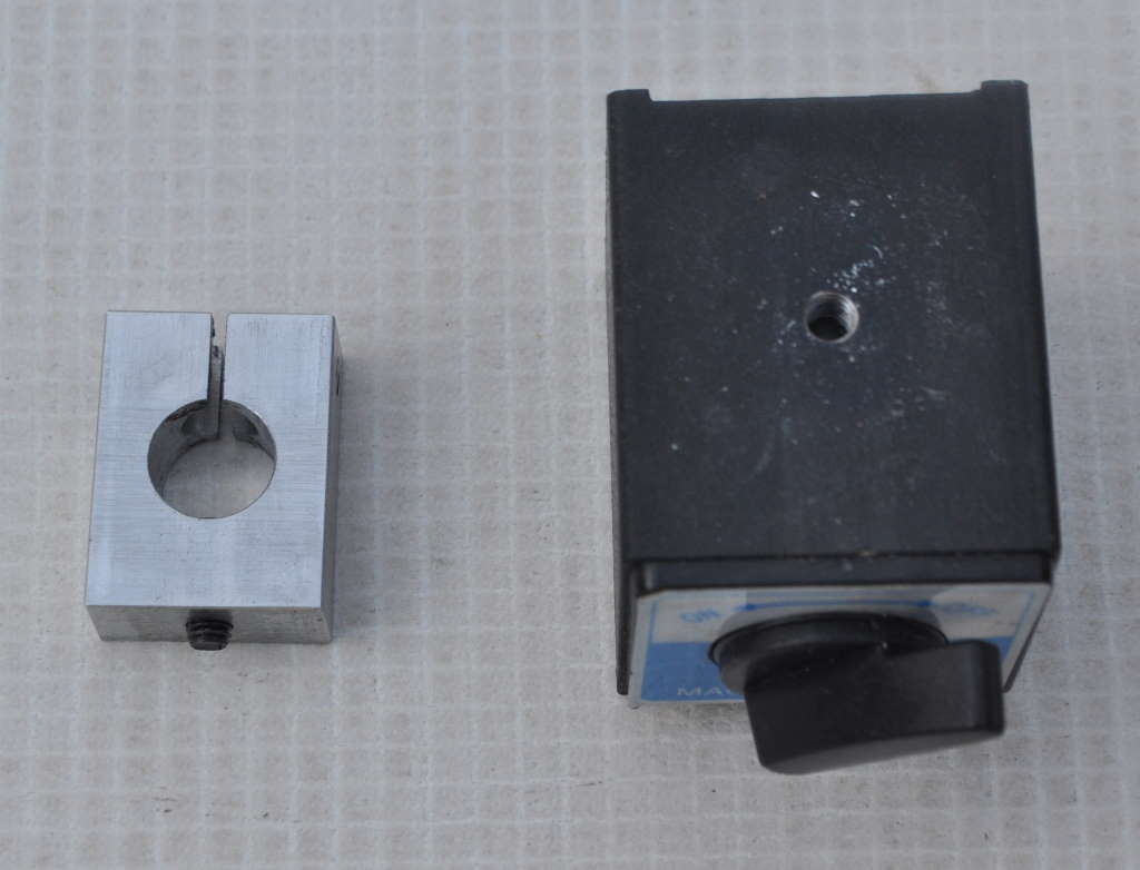
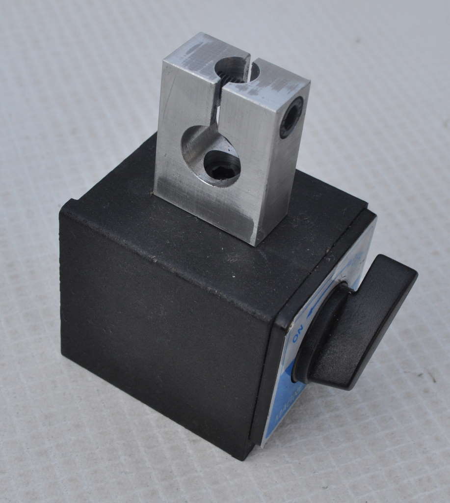
The bottom bar is attached to the magnetic bases using some 15 mm × 30 mm × 40 mm aluminium blocks. These have a central hole for a screw to attach the magnetic bases and then a hole, slit and clamping screw to hold the steel bar in place.
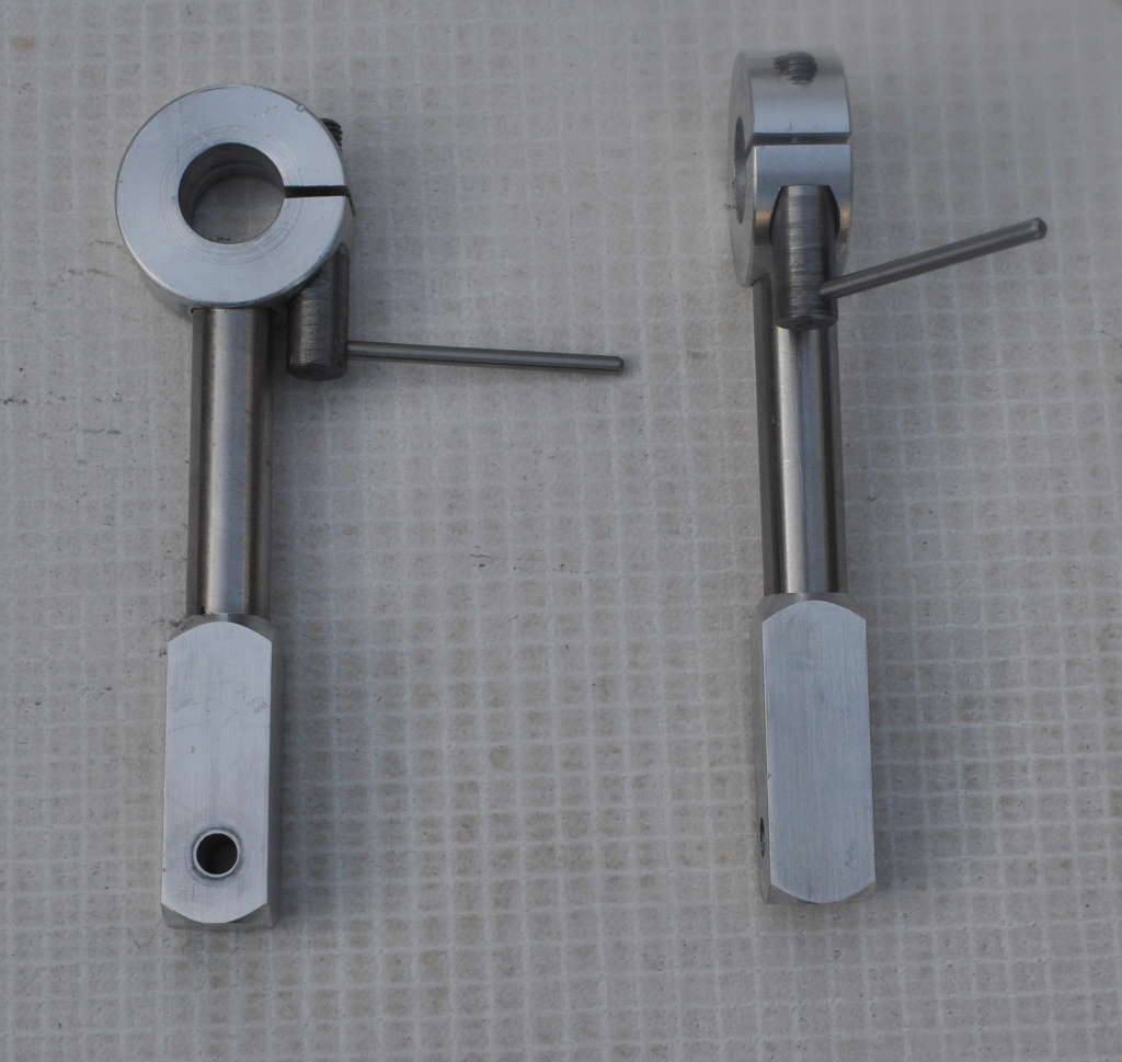
Attached to the steel base bar are some diagonal offset bars. These move the moving parts of the vice such that the centre of gravity is over the magnetic bases. They each consist of a three parts, held together with Loctite 603. The first piece is a 36 mm diameter piece of aluminium, 15 mm long with a slit and a custom-made steel clamping screw to hold the offset bar to the base bar. There is then a 12 mm stainless steel bar and a piece of 15 mm square aluminium with a cross hole for another screw to attach to the vice's fixed jaw. The offset piece is 100 mm long from the centre of the base bar to the centre of the vice-mount screw hole.
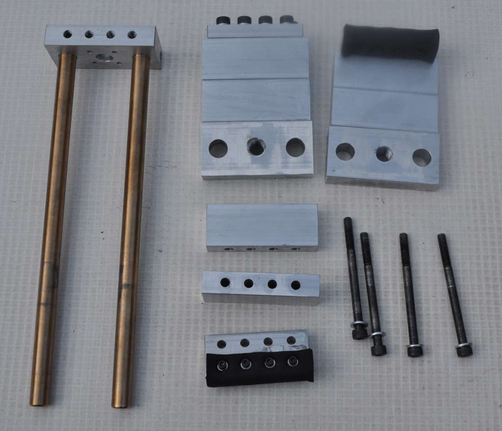
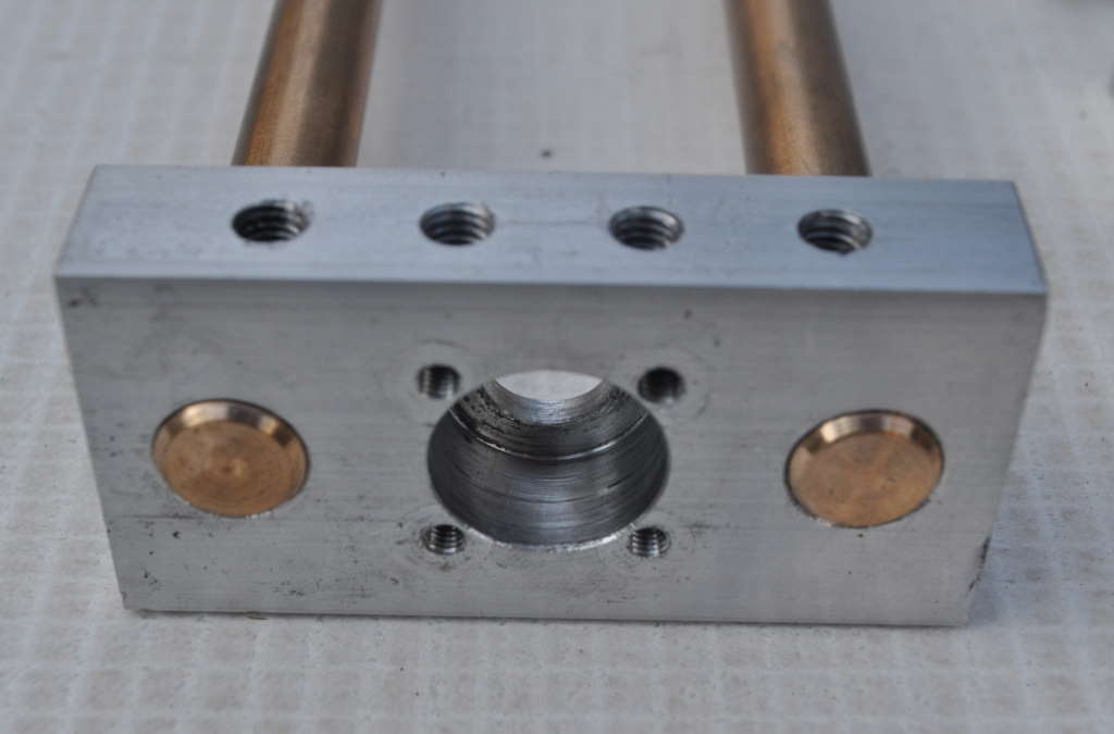
Each of the four vice jaws is made of four separate pieces of aluminium. The bottom piece is 15 mm × 75 mm × 40 mm with four M6 tapped holes in the top, two reamed 12 mm holes in the side and another hole in the side for the vice screw. In the rear of the two bottom pieces (the moving jaw), this is simply tapped M12; the front one (the fixed jaw) has a 12 mm hole through and then a 20 mm hole bored to a depth of 10 mm to retain the screw. The fixed jaw also has two M6 tapped holes on the sides to attach to the offset bars. The intermediate two pieces are 15 mm × 75 mm × 30 mm with four holes drilled for the mounting screws to pass straight through.
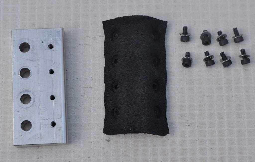
The top piece is 10 mm × 30 mm × 66 mm with through holes for the mounting screws and some M3 tapped holes for holding a piece of 3 mm thick neoprene in place to act as a super soft jaw. The slightly odd dimensions of all of those aluminium jaw pieces was a result of what I had lying around. The design intention (such as it was) was to allow different heights of the clamp above the vice screw by fitting or omitting different pieces of aluminium.
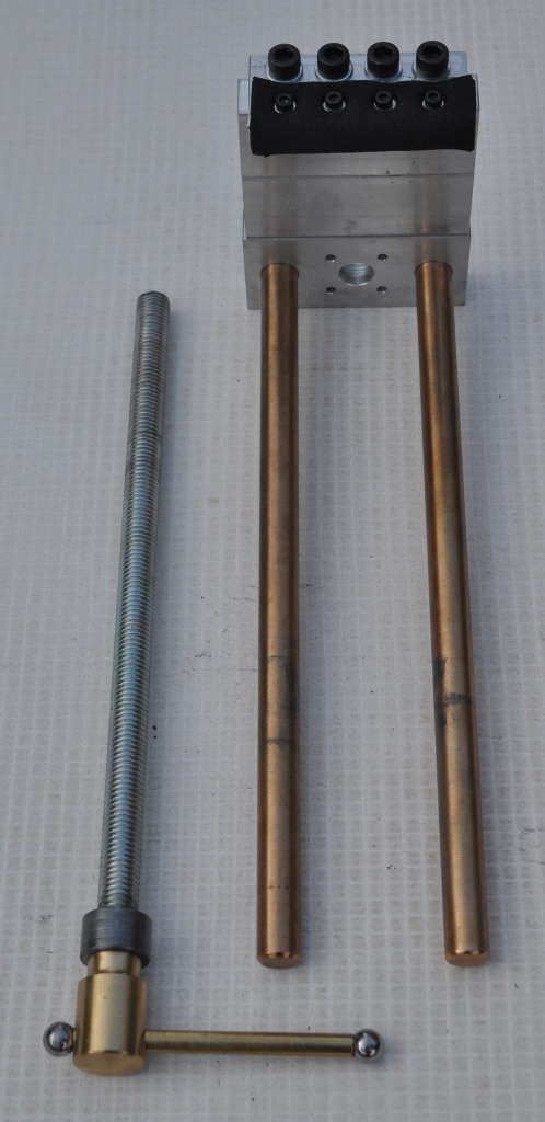
The bars that pass through the reamed holes (and are glued in the holes in the front vice jaw) are made of some sort of brass or bronze, 12 mm diameter. It came out of the skip and I've no idea what it is; it was partly as a sensible use of this scavenged material that I decided to make this vice...
The vice screw is mostly made from a piece of M12 threaded rod. A piece of 20 mm diameter mild steel was drilled and tapped M12 and cut to about 10 mm long. This was threaded onto the bar and held in place with Loctite 603 to hold the threaded bar in place in the front jaw. It is retained with four M4 cap-head screws with washers. These are tight on the aluminium block but not the mild steel retaining piece, allowing the retaining piece and its threaded rod attachment to rotate freely in the front vice jaw, but limiting it's movement back and forth.
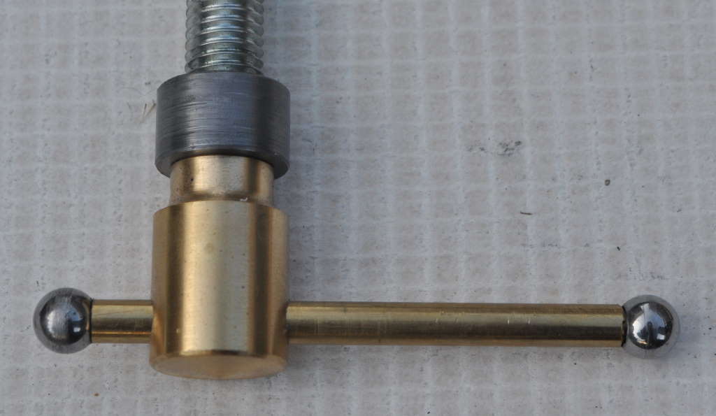
The handle for the vice screw was made out of brass. The body is 20 mm diameter and about 30 mm long. The inner and outer profiles were shaped manually using hand files on the lathe. The 5 mm cross hole was made first and then an M12 hole was drilled and tapped in the rear of the handle. The hole was drilled far enough to break into the cross hole. A small disc of neoprene was inserted into the tapped hole prior to threading (with thread-lock) onto the vice screw; the neoprene presses slightly into the cross hole, giving some friction against the cross bar and stopping it from sliding around.
The cross bar is a piece of 5 mm brass bar, about 85 mm long. The balls on the end were off-the-shelf unhardened steel balls, 10 mm diameter, which I drilled and tapped to accept the ends of the brass cross bar.
That's really "all" there is to it! A completely pointless project that I think looks quite good and I thoroughly enjoyed making. It does serve the purpose of gently but firmly holding the boat model in place (although undoubtedly there are simpler ways of achieving that); I just need to put aside some time to actually work on the boat and finally make a bit of progress...
This website is free and ad-free, but costs me money to run. If you'd like to support this site, please consider making a small donation or sending me a message to let me know what you liked or found useful.
