Heat Treatment Oven
This is my heat treatment oven: an oven used to heat bits of steel up to very high temperatures (around 800°C typically) before quenching in oil or water to harden the steel. In theory the oven could go up to around 1250°C (the maximum rating of the various materials used in the build) but in practice I'll limit it to around 1000°C to leave some head-room from the absolute limit.
In the past I've hardened steel parts using a blowtorch and I expect that I'll continue to do so for small parts where the blowtorch is able to heat them up quickly. For larger parts, I struggle to get enough heat in with a blowtorch and it can also be tedious holding the part at high temperature for long enough (the usual recommendation is an hour per 25 mm thickness: for 3 mm thick parts that's only 7 minutes, but it's still a long time to be standing holding a blowtorch after the part has got up to temperature). Another advantage of a heat treatment oven is that it heats the part more consistently (rather than focusing the heat on the cutting edge), which can reduce distortion.
As with many of my recent builds, I documented the process I went through to build the heat treatment oven, from initial concept through to completed build. You can read that build log by following this link.
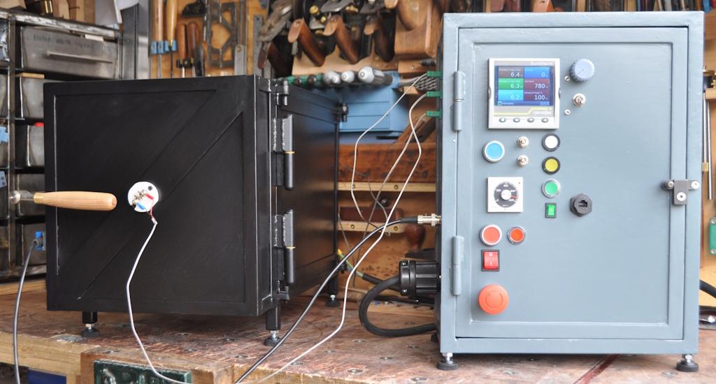
Unlike many of the builds I've seen elsewhere on the web, I decided to make the control cabinet and the thermal chamber as separate entities. The main advantage to this is that I can re-use the control cabinet for other chambers (for example if I make a casting furnace, which is more likely to be oriented with the door at the top). The other advantage is that it reduces the weight of any individual part. I don't have space in my workshop for this to stay there all the time so it was important to me that I could move it around relatively easily. The chamber door comes off easily, so I can move the chamber body, then the door, then the control cabinet and each individual object is manageable.
This photo shows a side view of the chamber and its control cabinet. On the chamber you can see the latch that holds the door closed as well as the safety interlock that cuts off power to the chamber when the door is open. I mounted the interlock on the door so that the cable was easy to route alongside one of the thermocouple cables.
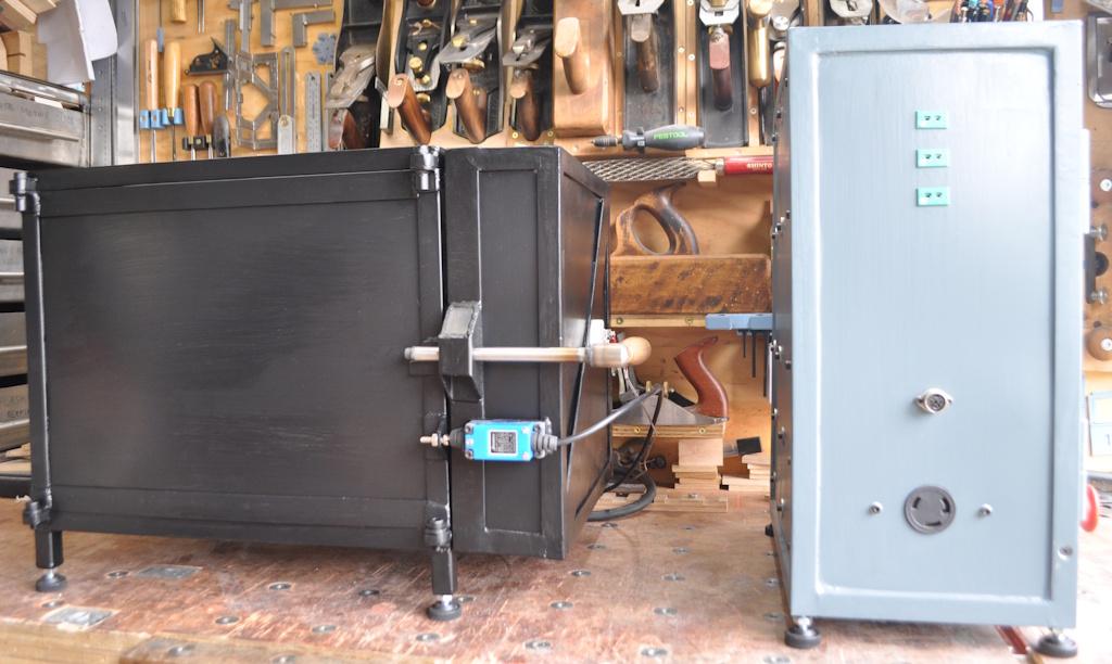
On the left-hand side of the control cabinet there are five connections: a power connection at the bottom (going to the heating element), the interlock connection above that and then three green (the standard IEC colour) K-type thermocouple connections at the top. The top thermocouple input is used for controlling the temperature, the middle one is for monitoring temperature at another point in the chamber and the bottom one goes to a safety cut-off, which will cut power to the chamber if the controller goes haywire and the temperature gets too high.
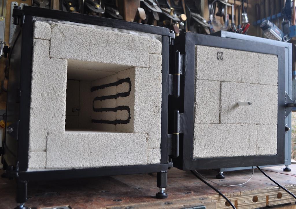
This photo shows a view inside the chamber. There is one thermocouple mounted in the door which you can see on the right. The other two are mounted in a similar manner at the back of the chamber. The element is wound from some Kanthal A1 element wire and set into slots in the insulating fire bricks.
Unlike many builds I've seen online, the bricks are not mortared together: they're just held in place by friction and the frame around the outside. When I was writing up the build on the MIG welding forum, I had lots of good advice from various members who had built several of these chambers in the past and the consensus was that mortar was unnecessary.
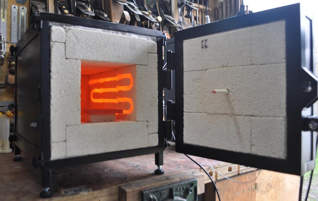
This photo shows a similar view, but with the door opened after the chamber had been held at 780°C for half an hour or so to heat up a piece of 12 mm × 100 mm × 100 mm steel (just for testing), which you can see sitting on an off-cut of insulating fire brick in the photo.
My original plan had been to make a single chamber that could be oriented horizontally for heat treatment or vertically for casting, but during the build I realised that this wasn't really viable. The main problem with the idea is that the element wire can sag under its own weight when it is at high temperature. If I oriented the chamber on what is now its back, the element could stretch near the door and compress near the back, which would not be good. Trying to make a single chamber serve both purposes would also would have resulted in less-than-ideal placement of the thermocouples. By having the control cabinet separate, it should be relatively straightforward to make a second chamber (this one vertically oriented) specifically for casting.
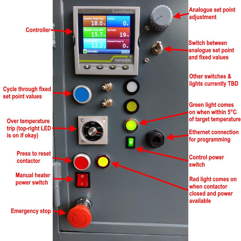
This photo (click on it to see a bigger view) shows a detail view of the front of the control cabinet along with an explanation of what the various knobs, buttons, switches and lights do. While I was writing up the early stages of the build on the MIG welding forum, a very generous member of that forum offered to send me (free of charge) a selection of control gear that he had. Through his incredible generosity (which I repaid in part with some thank you gifts shown on another page on this site), I was able to use a very advanced controller (supporting several inputs and also programmable ramps & dwells and such-like). There's also a thyristor current controller in the cabinet allowing me to run the chamber at a reduced current if desired.
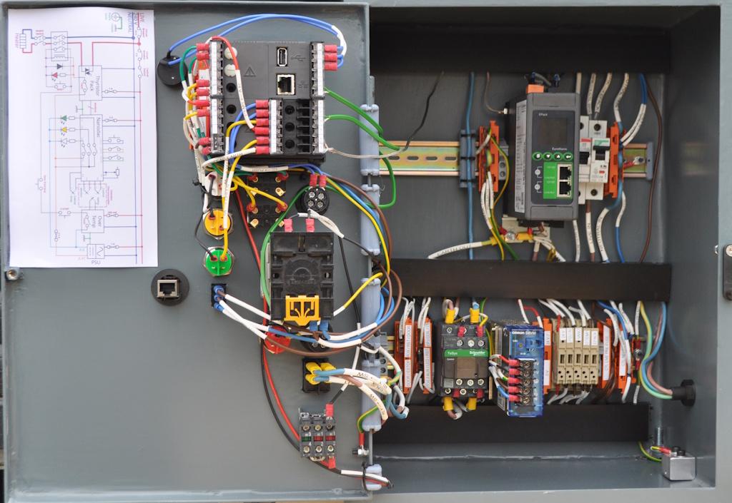
This photo shows a view inside the control cabinet (with two ethernet cables removed to give a better view). The photo was taken before the final switch (beneath the potentiometer on the previous photo) was added.
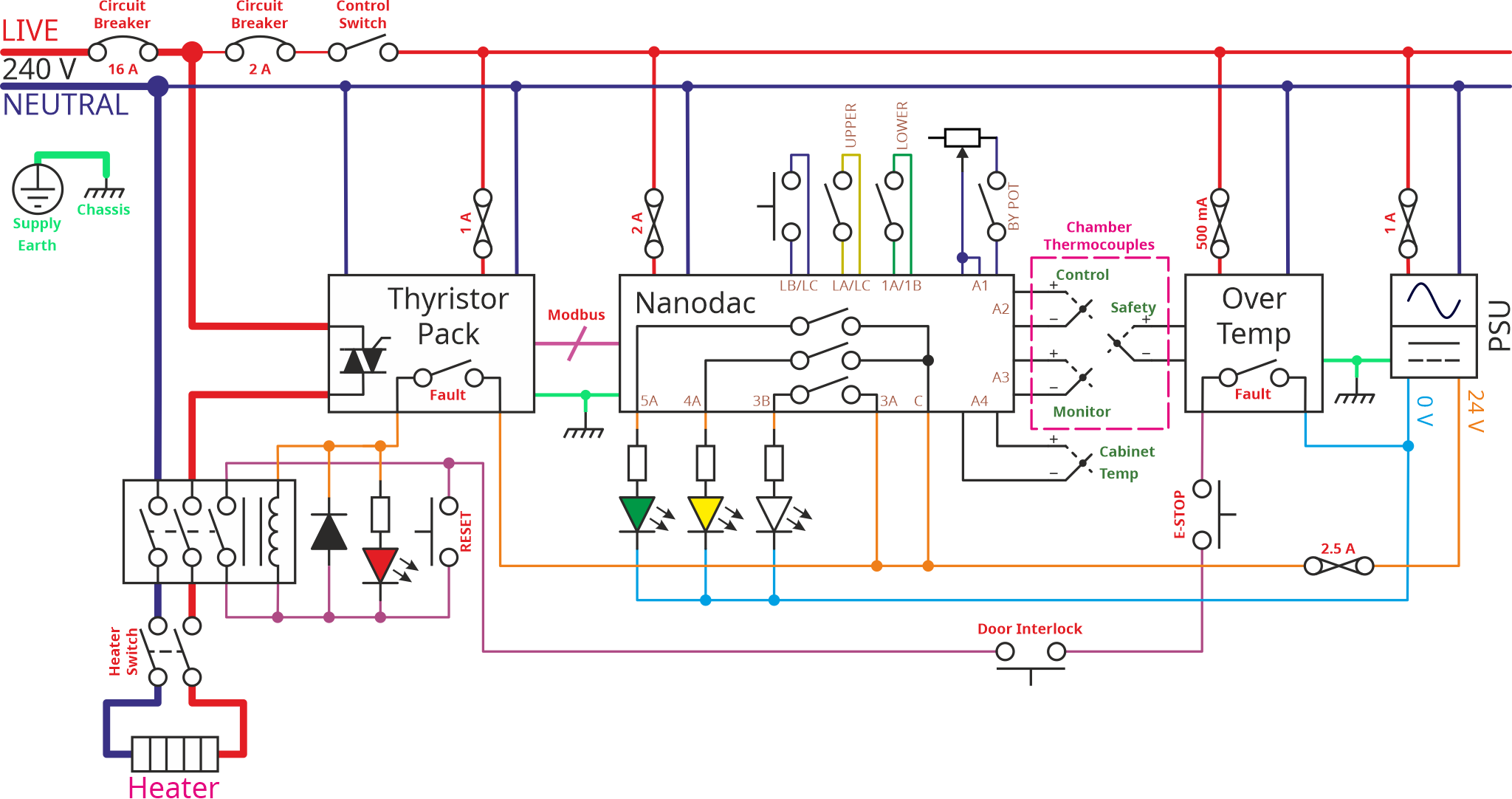
This is the schematic showing what's going on inside the control cabinet. The details of this schematic are explained in great detail in the build log, with the schematic explanation starting on page 7.
This website is free and ad-free, but costs me money to run. If you'd like to support this site, please consider making a small donation or sending me a message to let me know what you liked or found useful.

