Mini Moravian Bench Build Process
Page 31 of 38
Posted 8th August 2025
I can imagine some people won't approve of the number of jigs I'm going to use over the next few posts, but tough! There has been quite a lot of heartache in this project so far and I've got a lot of work invested in the pieces I've prepared so far. I'm seriously nervous about cutting the joints to attach the top (which I've now decided for certain will be tapered dovetail housings) and I want to give myself the best chance of a good result.
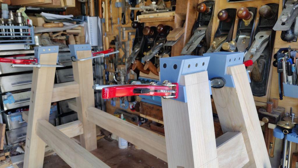
To that end, the 3D-printer has been running pretty much constantly all week, producing a whole host of little widgets that you'll get to see over the next few posts. The first four of these can be seen clamped to the tops of the legs in this photo:
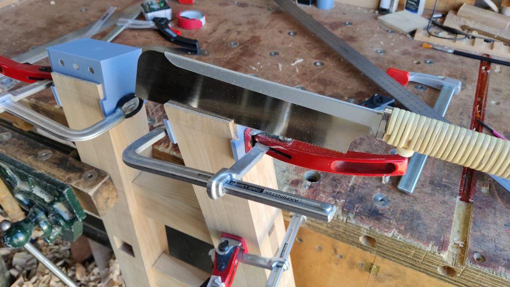
They're saw guides, with magnets embedded into the angled faces to guide a saw at the right (compound) angle for the sides of the dovetails. After spending quite a while tweaking their position (with the frame assembled so that I could check their position relative to each other as well as to the legs), I dismantled the frame, clamped a leg to the side of the bench and used a Dozuki to saw the first side of the first tail, letting the magnets guide its path:
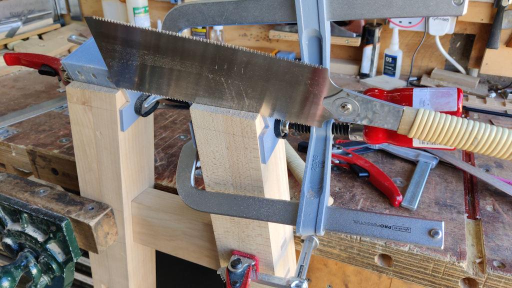
That was quite hard work (and I found that the clamp was getting in the way a bit), so I switched to the Ryoba for the rest of them (and added some different clamps, being sure not to let the jig move in the process):
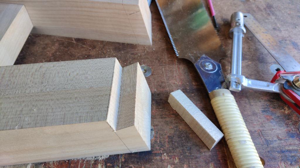
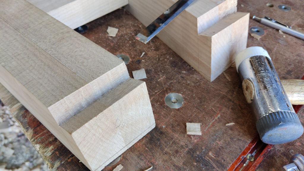
I then clamped the leg to the bench and again used the Ryoba, this time to cross-cut a millimetre or so away from the shoulder line:
I'd scribed a knife line for the shoulders, but I'm not sure whether it's that accurate in terms of the position on one leg frame relative to the other. However, I figured that with the leg frames being about 800 mm apart (at the top), a small discrepancy probably doesn't matter that much. Nevertheless, I could use that knife line to guide a chisel for a cleaned up shoulder:
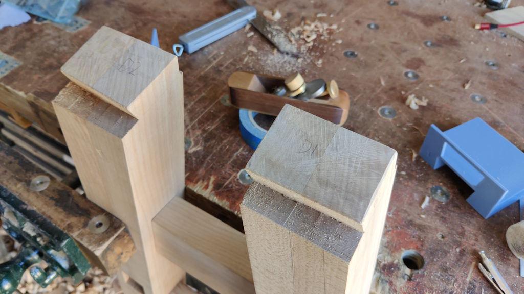
Before moving on to the next stage, I used my little home-made block plane to tidy up the end grain (after planing a chamfer all round to minimise the risk of break-out).
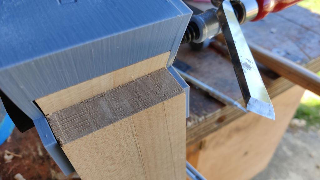
It was then time for the next set of jigs (one for each leg), which look very similar too the first ones:
The differences between the two sets are that:
- These ones don't have magnets embedded into the reference faces;
- These ones are slightly narrower (1 mm on each side) so that the chisel can be used to pare off the last little bit of the face to get it down to the target size.
I'll be able to re-use those chisel jigs (offset slightly) again if I need to tweak the size of the tail later.
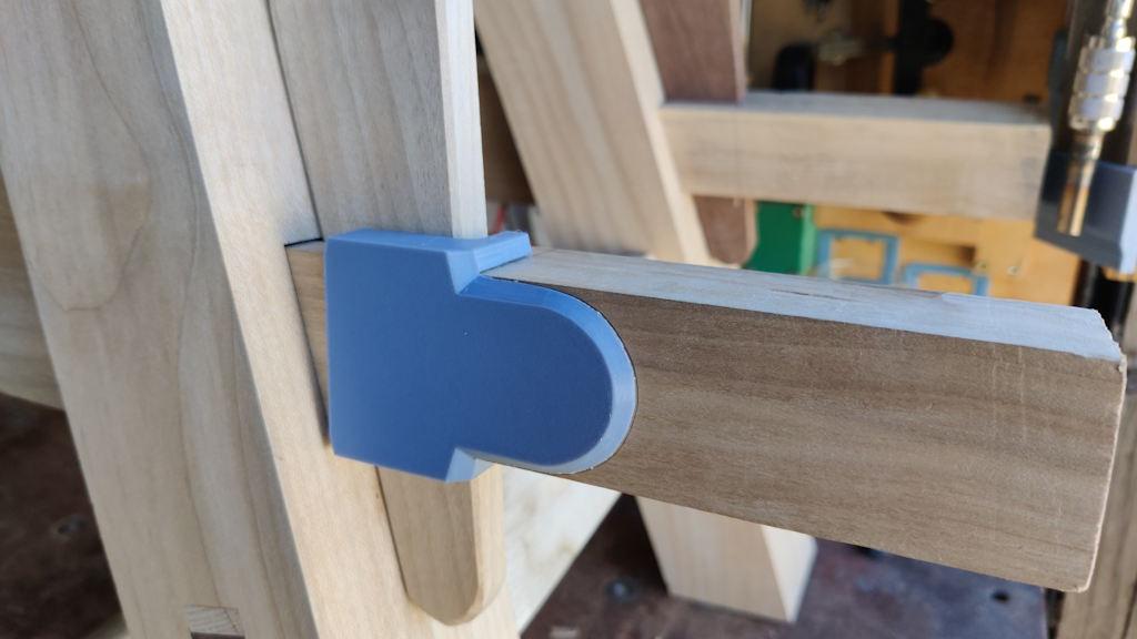
With that done, I assembled the frames again and used another simple marking gauge (referenced on the outer edge of the bottom of the wedge) to draw the shape of the ends of the stretchers (which I'll cut down at some point much, much later).
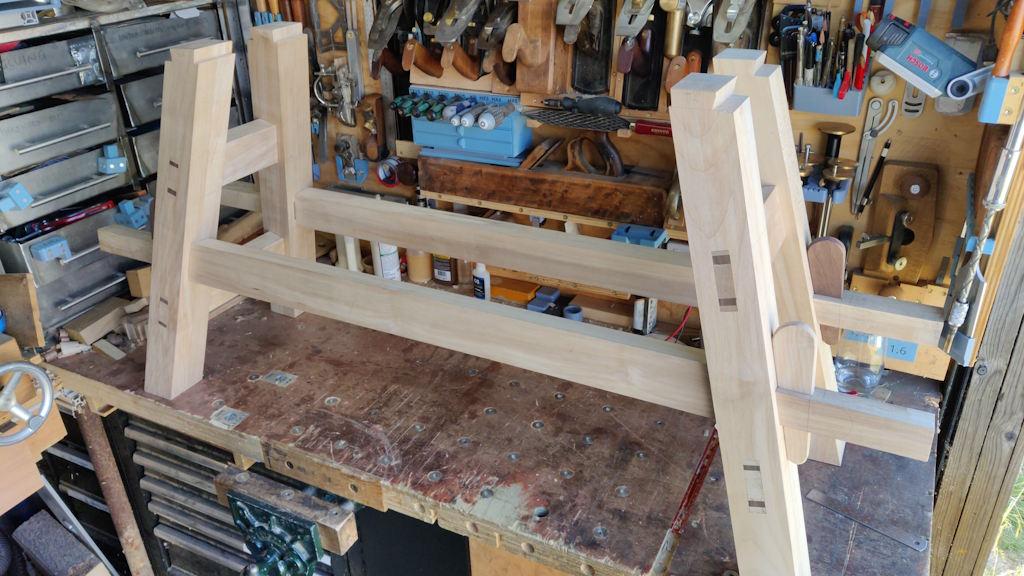
The next photo shows the frame as it is at the moment, with all the dovetails on the top ends of the legs cut. Hopefully they're in the right place, with the right tail angle and the right taper angle!
The next job will be to plane the top pieces smooth and square. I might just do the bottom and inside faces for now and leave the others for later, but I don't want to start on the dovetail sockets until I've got some sort of reference to work from.
Page 31 of 38
This website is free and ad-free, but costs me money to run. If you'd like to support this site, please consider making a small donation or sending me a message to let me know what you liked or found useful.

 Return to main project page