Garden Table Build Process
Page 24 of 38
Posted 25th May 2025
I've been playing with more sweet chestnut since finishing (apart from glue and final planing) the table top and I'm now starting to feel a little bit more confident that my plan for the base might be achievable. This seemed like a good time to write about it in the hope that any major flaws will be pointed out before I do anything irreversible.
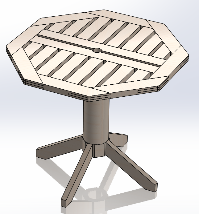
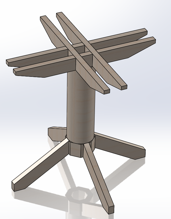
The plan is to have a column (probably circular, possibly octagonal) that goes up the middle. There will then be four legs going diagonally down to the ground and a cross thing at the top to support the table. This is what I'm hoping it'll look like:
I've drawn that with a mostly circular column with an octagonal bit at the bottom, but more likely I'll make it either entirely circular or entirely octagonal. Octagonal would make the mortice and tenon joints for the legs a lot easier, but I think circular might look better. Another compromise option would be to make it circular and then plane some flats near the bottom, just wide enough for the legs.
Thoughts/opinions welcome as always.
Making that central column would involve eight planks glued together and then (if I go for a circular column) turned into a cylinder on the home-made lathe (which I think has a bed that is just long enough!). I did a bit of research into making segmented turning blanks and all the advice said "make the blanks by setting your table saw's blade over at an angle". I don't have a table saw any more and I really don't want there to be a reason why I need one!
As an alternative, I tried doing a web search for how to make segments without a table saw. The general advice seemed to be "find someone with a table saw who can do it for you". I saw one post where someone asked if there was any way to do it with just a bandsaw and there were eight or nine answers, all of which could be summarised as "no". Not quite what I was hoping for!
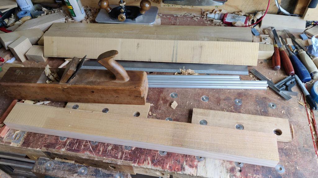
Nevertheless, a plan gradually formed in my head while I was working on the table top and with it out of the way I decided to have a go. I started by preparing quite a lot more sweet chestnut plans. I had one (planed on four sides) left over from when I prepared the material for the slats and the size seemed reasonable: according to my Regular Polygon Calculator, it should allow me to make a cylinder about 115 mm diameter, with an octagonal hole through the middle that's about 55 mm across-flats. Therefore, I decided to plane all the others to the same size as that one.
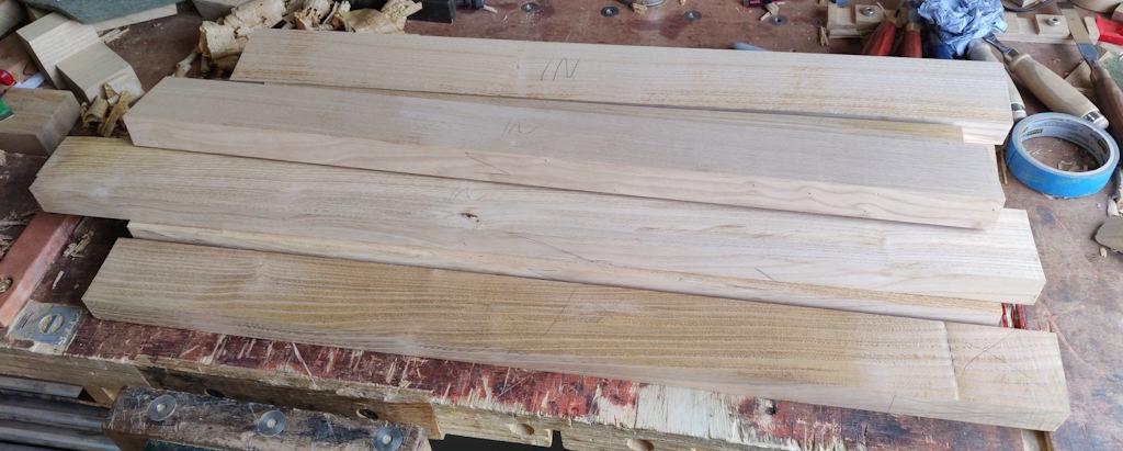
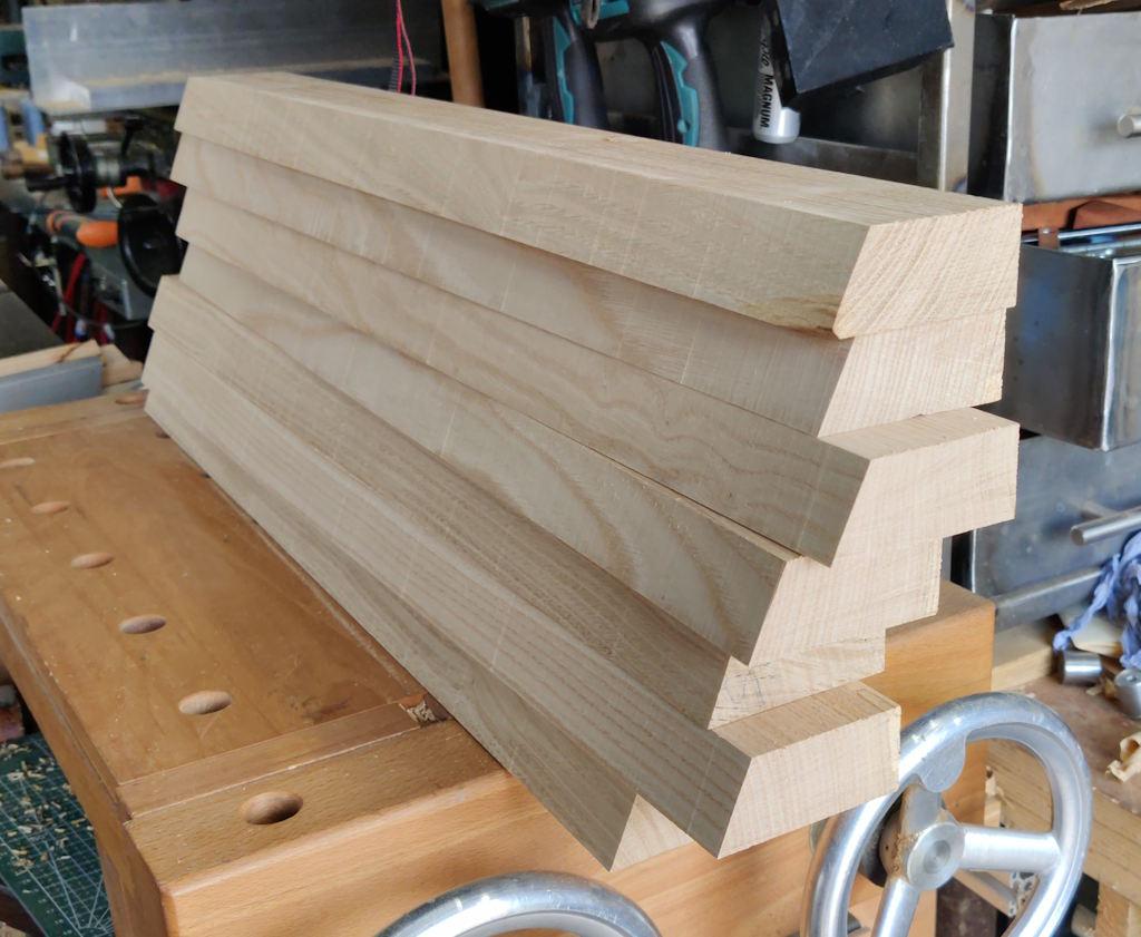
All done and ready for the next stage:
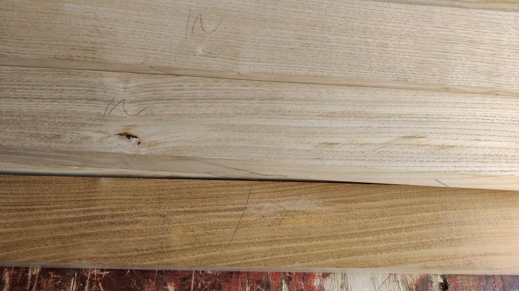
With the exception of the one I'd previously prepared, I labelled one side of each piece as "IN": this was chosen based on blemishes/knots mainly: if one side had more imperfections, I picked that as the side that would become the inside of the "tube":
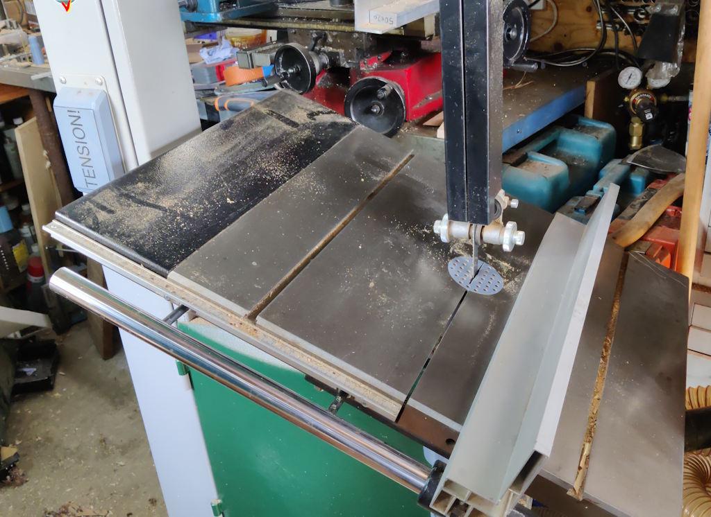
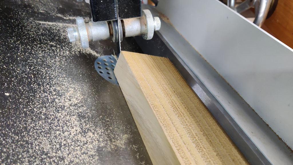
While I could possibly attack this problem purely with hand tools, I think it would stretch my skills a bit beyond what I'm capable of. It would also take a very long time, which would be frustrating if all the wood ends up as scrap at the end (a very real possibility!). Instead, I decided to use the bandsaw. First of all, I tilted the table over to 22.5° (measured with one of those little digital angle gauges that come in handy for all sorts of things) and moved the fence over to the down-hill side of the table. The latter job involved flipping the support bar over as it's longer on one end than the other and the longer end was pointing up-hill.
The fence support rail is only just long enough for what I need to do, but it is long enough.
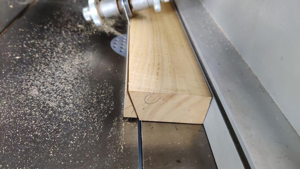
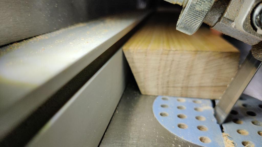
The first cut was done by running a flat side of the narrowest piece (which was the one I'd prepared as part of the slat preparation) against the fence and feeding the plank through the saw:
That left a slightly rough face (as you'd expect from a bandsaw) but at roughly the right angle.
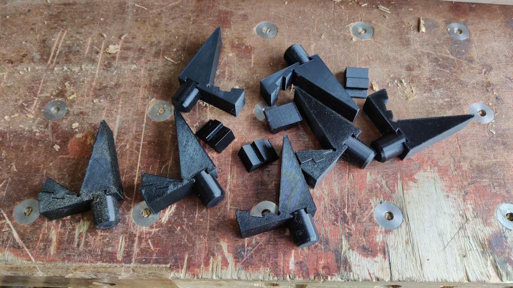
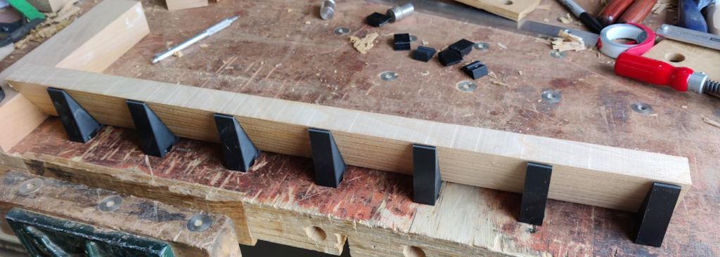
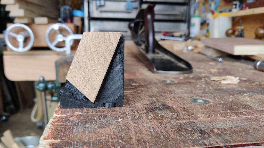
During the week, I'd 3D-printed some little supports, each made in three pieces - a main support, a 20 mm diameter cylinder to fit the dog holes on the bench and a little wedge that fits into the notch on the main support:
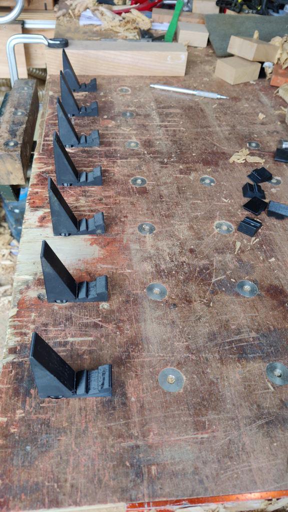
Those supports drop into the dog holes on the bench and with the wedge inserts removed and a handy bit of scrap clamped in place as an end-stop...
... I was ready to to plane that rough surface away:
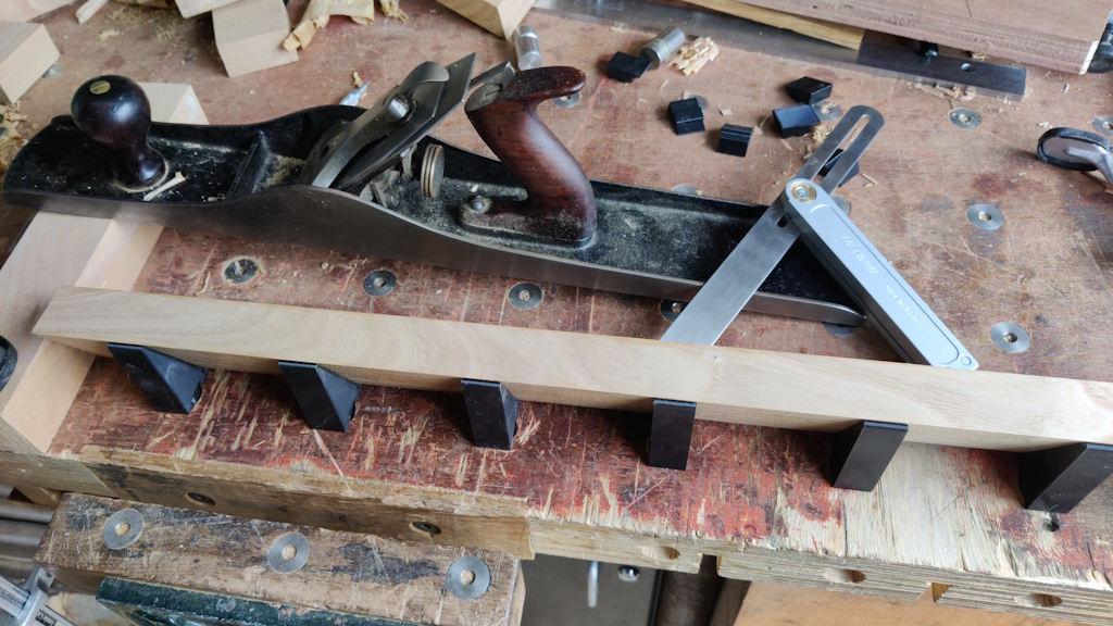
The planing job was quite ergonomic as I'm planing parallel with the bench top. I set a sliding bevel to 67.5° and used it, in combination with the slightly cambered blade on the #7, to prepare the edge in much the same was as I would normally prepare an edge square to a face:
Before starting on the second side of that plank, I fed the other seven pieces through the bandsaw to do the rough cut on the first side of each of them:
The reason for that is that I could now set the bandsaw's fence up for the second cut and (give or take any planing discrepancies) they should all end up the same width.
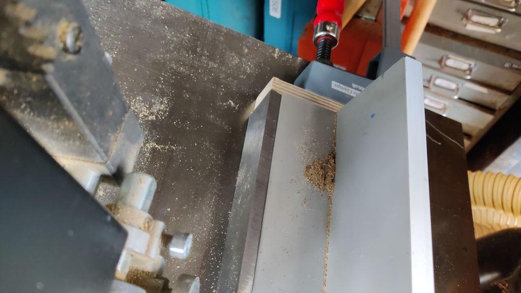
When I came to start the second cut on the first piece, I found that the little cut-out (for mounting accessories) in the fence was at almost exactly the wrong height:
I didn't think it was a good idea to try sawing like that, so I had a rummage around in my various drawers and found a piece of 8 mm × 40 mm × 500 mm gauge plate. That got placed against the fence and then I used a clamp to hold an off-cut of plywood onto the end of the fence to stop the piece of gauge plate sliding forward with the wood:
I could then feed the plank through with the corner of the first prepared side pushed up against the steel bar:
The little wedge pieces were then inserted into the support blocks and the support blocks spun round (to suit the grain direction) and I could repeat the process of preparing an edge at the right angle, with #7 and sliding bevel to check:
That brings us up-to-date. Tomorrow, I'll prepare the other seven blanks (which, so far have only had one side rough-cut). Then they'll need to be joined together. At the moment, I'm thinking I'll just do that with glue (and lots and lots of masking tape!). Alternatively, I could put some sort of spline in each joint (perhaps by ploughing a groove in the edges I've just planed and then inserting a long and relatively thin bit of wood in the groove). Do you think this is necessary? I think of long edge joints as being strong enough with just glue, but I'd like to hear other people's thoughts before it's too late!
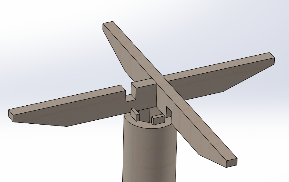
Going back to the model, this is what it will (probably, hopefully?) look like with the top removed:
I haven't really figured how to attach those cross pieces to the central column. At the moment, the CAD model has some half-lap joints where the cross-pieces intersect and some sort of (probably impossibly to cut how I've drawn it) mortice and tenon joining the column to the cross pieces:
As well as the thoughts on cylinder vs octagon and on splines vs simple glue joints, I'd also welcome any thoughts on this support design and the associated joinery.
Page 24 of 38
This website is free and ad-free, but costs me money to run. If you'd like to support this site, please consider making a small donation or sending me a message to let me know what you liked or found useful.

 Return to main project page