Bar Clamps
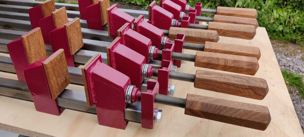
These are some bar clamps that I made based on an idea from Neil Paskin.
They're based on some lengths of 25 mm × 25 mm × 2 mm box section. Each piece of box section has had a length of M12 threaded rod welded along the underside. The sliding jaw (left-most in the image at the top of the page) slides freely along the bar when tilted forward, but there's half an M12 nut on the bottom that engages with the threaded rod when tilted back. The pressure of tightening the screw on the other jaw and pressing against the sliding jaw forces the M12 half-nut into the thread.
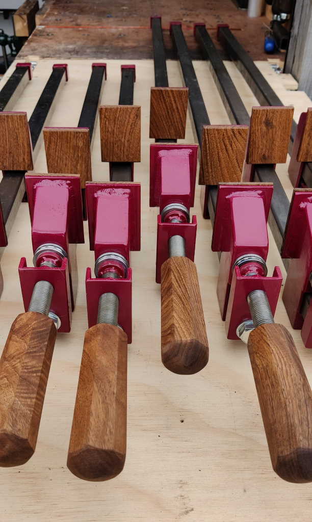
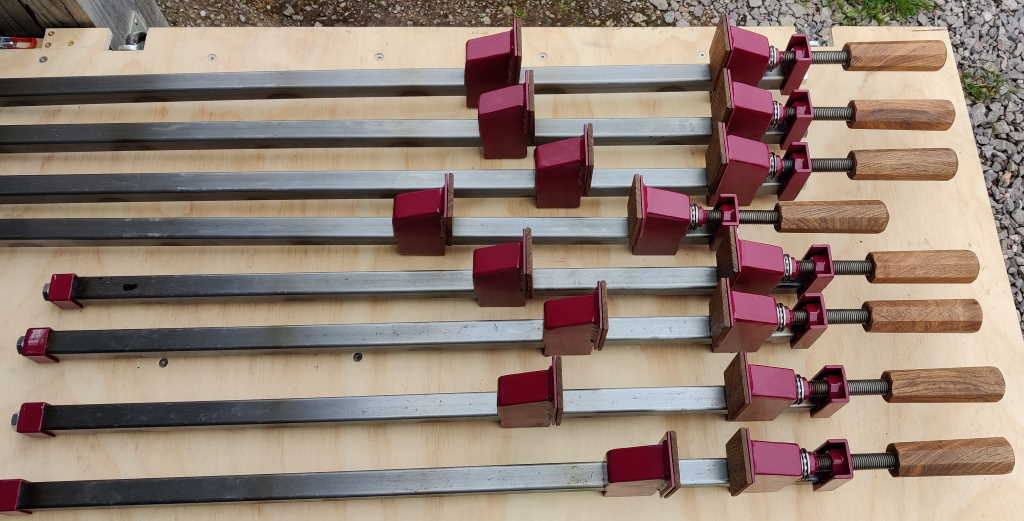
This shows another view of the clamps. There are eight clamps that I've made. Four are based on 800 mm bars and have a maximum clamping length of 620 mm. Four are based on 1.2 metre bars and have a maximum clamping length of 1020 mm. Unlike Neil Paskin's design, the heads on my bar clamps are held in place with M12 hex head set screws (Neil welded his screw jaw end plates in place). This allows the jaws to be removed and fitted onto different bars; I have made four 1880 mm bars, which can be used when I need a clamping length up to 1700 mm. Apart from dimensional changes I didn't make many significant modifications to Neil Paskin's design (or at least what I could work out of Neil Paskin's design based on the video), but I did add some reinforcement plates on the sides of the end plates and some thrust bearings between the screw jaw and the nut that pushes it.
Adjusting the position of the sliding jaw is very quick: by tilting the head forward it becomes freed from the threaded rod on the bottom of the bar and can be slid up and down the bar to the desired position. One advantage of this type of bar clamp is that the sliding jaw can be adjusted in increments of 1.75 mm (the pitch of the M12 threaded rod). That means that you don't need a very fast (coarse pitch) thread on the screw jaw as it never needs to move very far.
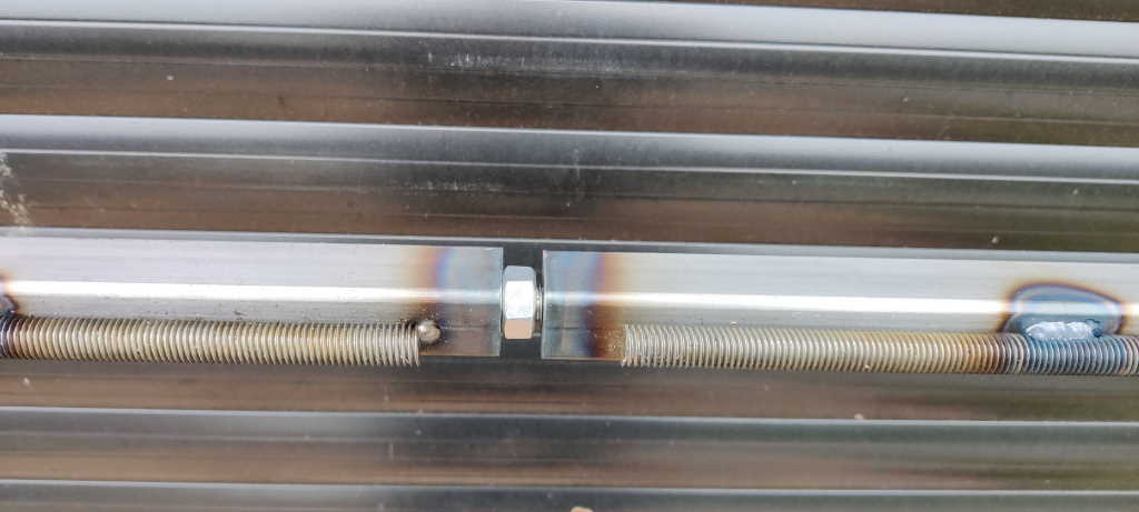
Having removable heads and end caps also means that multiple bars can be joined together. Here I've used a short length of M12 threaded rod (with a nut to stop it turning after being inserted into the first bar) to join two bars together. I used one of the longest bars and one of the medium bars to make a clamp that is capable of clamping across the outside of the width of my single garage.
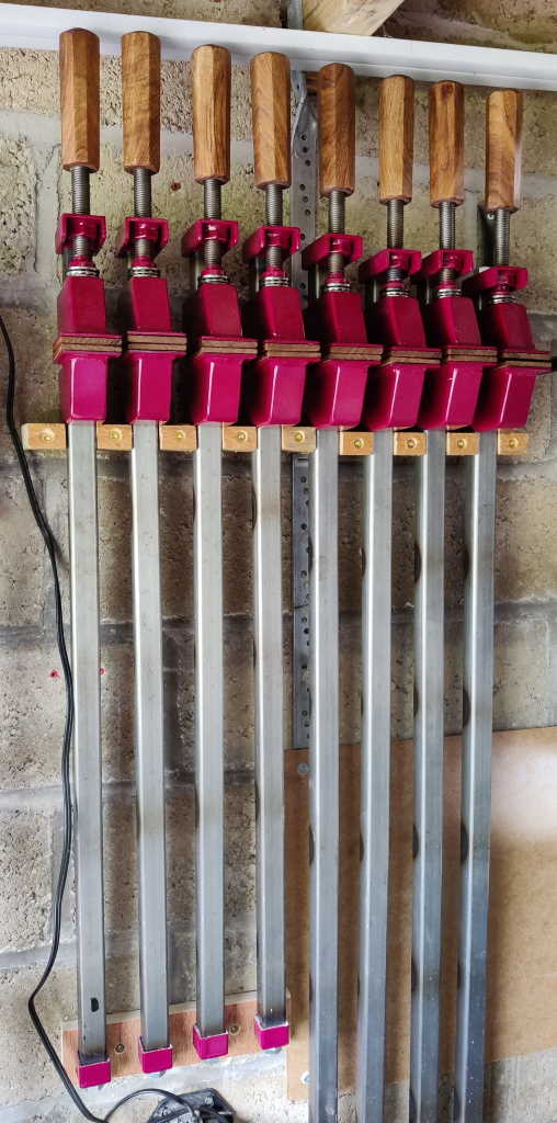
This photo shows the bar clamps stored in a simple rack.
Build Log
There is a lot of extra detail about how the stages I went through to make these bar clamps in the build log.
A 3D Model
If you have a relatively modern browser, you should be able to drag the model below around with your mouse to look at it from different angles. The left mouse button will rotate the part, the right mouse button moves it and the scroll wheel zooms in and out. On mobile phone browsers, one finger rotates the model while two can be used to pan and zoom. Note that the model may take a few seconds to load.
If you'd like a copy of the .STEP file for this CAD model or the cutting list with the dimensions of the parts, please get in touch.
This website is free and ad-free, but costs me money to run. If you'd like to support this site, please consider making a small donation or sending me a message to let me know what you liked or found useful.

