Top Slide Motor
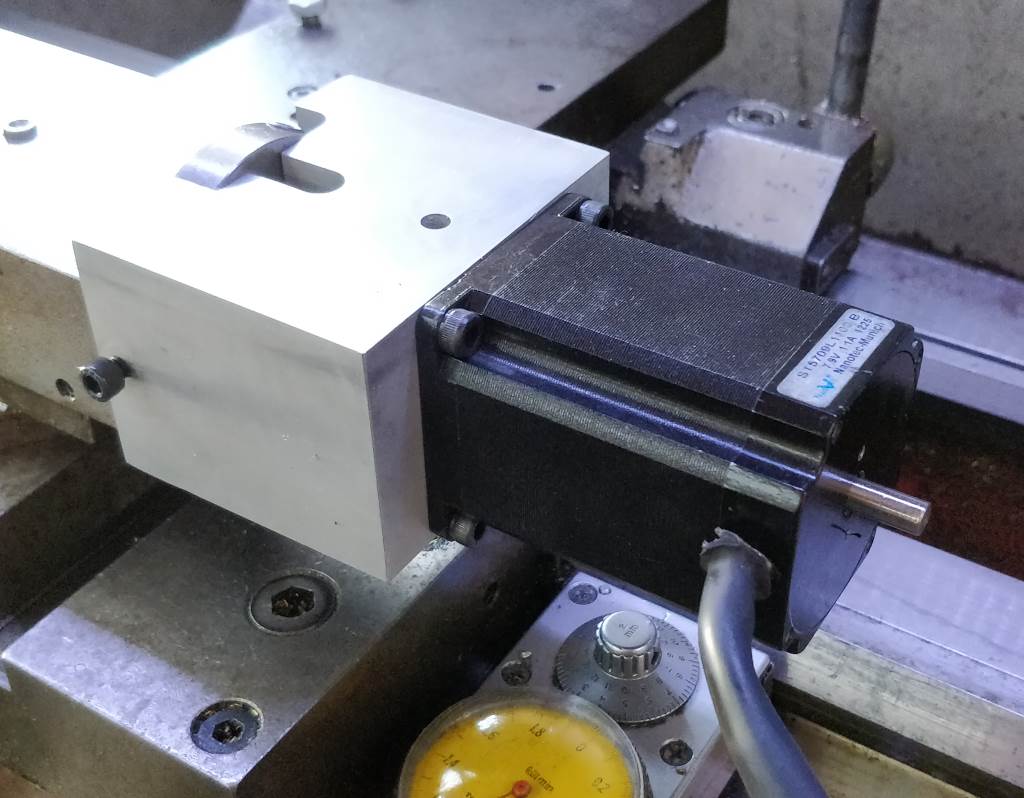
I mentioned on the main M250 page that I've never mastered getting a really good finish when turning hand-wheels by hand. Mostly this isn't a problem as I take the final cuts with the powered fine feed either for skimming the outer diameter or for taking smooth facing cuts. However, there are many times when I want to turn a short taper using the top-slide and I have to get back into practising fine finish hand-wheel turning (or touch the surface up with a smooth hand-file afterwards).
Buried in one of my drawers, I had a selection of small (NEMA23) stepper motors. I had previously used one of these to convert my rotary table to being stepper controlled and I bought a DivisionMaster Full Kit to power it. The DivisionMaster has a "continuous mode", which can be used for running a stepper motor continuously in either direction. This struck me as ideal for moving the top-slide. It doesn't have end-limits, but as long as I have my finger over the "stop" button, this isn't really a problem. At a push, I could probably configure the settings such that one "division" was the amount of movement that I wanted the top-slide to move, but I haven't felt it's worth the effort at this point. I may do this (or make my own stepper controller) when I next want to turn a taper up to a consistent point.
Edit:I have since modified one of the configuration sets in the DivisionMaster so that the "degrees mode" can be used for accurate positioning. The leadscrew in the top-slide is 2.5 mm pitch: this implies that 360 mm of movement would be 144 turns of the motor (360÷2.5). However, the DivisionMaster assumes a 200 step-per-rev motor whereas the one I use has 400 steps-per-rev. Therefore I doubled the calculation to give a "worm ratio" of 288. Once this is configured into the DivisionMaster, the "degrees mode" gives 1 mm movement for 1° so it's very easy to take controlled cuts.
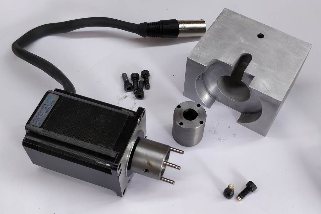
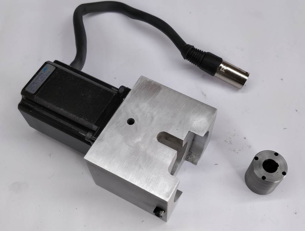
The photo on the left shows the parts that make up the top slide motor assembly. The male dog (attached to the stepper motor) is 28 mm diameter and 20 mm long. It has a 1/4" bore to match the shaft of the stepper motor. It has four 3 mm diameter holes on a 24 mm PCD, sized to be a tight fit on some 3 mm dowel pins I had in a drawer. The dowel pins are glued in place with Loctite 603. The male dog is cross-threaded M5 for a grub screw to hold it in place on the stepper motor shaft (which has been filed to have a flat on one side). The end with the dogs sticking out has a recess, 20 mm diameter and 5 mm deep. This is a space for the mounting screw and washer to sit: shown in a later photo.
The female dog is 28 mm diameter, 32 mm long with a 12 mm bore keyed with a 3 mm wide slot. There are four 3 mm diameter holes, sized to be a loose sliding fit on the dowel pins that are used as drive dogs.
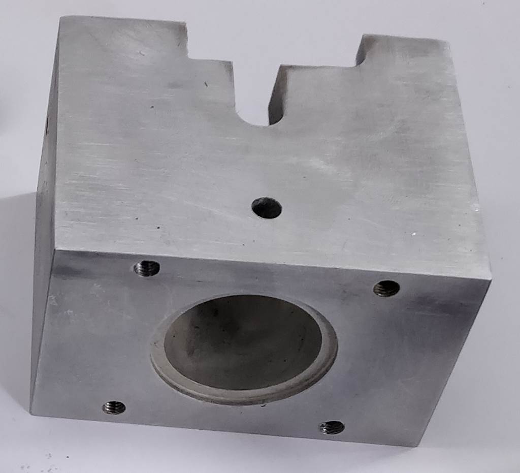
The body (the size of which was largely based on available material) is 70 mm × 85 mm × 57 mm. The end that attaches to the lathe is bored 63.5 mm (2.5") to a depth of 12 mm. It has been opened up on one side (using an end mill) to give clearance around the oiling point. There is an M5 threaded hole on each side to clamp it to the lathe. The other end is machined to fit the stepper motor features: a 38.1 mm (1.5") bore to a depth of 2 mm and four threaded holes to match the fixing locations on the stepper motor.
The slot that can be seen in the top was originally envisaged to help separate the two dogs, but this isn't needed. The hole that can be seen in the top is located over the grub screw that holds the dog to the stepper motor. Again, this isn't really needed.
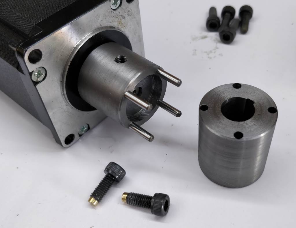
The screws in the bottom of this photo are used to clamp the body onto the lathe. They are standard M5 cap screws that have a 2 mm hole drilled a few millimetres into the end. A short brass piece, 4 mm outer diameter was reduced to 2 mm for a few millimetres and this is glued into the end of the cap screw with Loctite 603. This is intended to reduce any marking on the lathe.
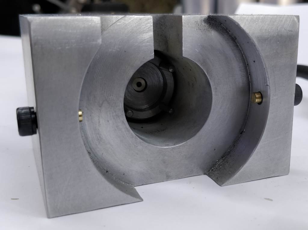
These photos show the top slide assembled (in the form it spends most of its time when not on the lathe). The right-hand photo shows how the brass-ended screws protrude into the main bore.
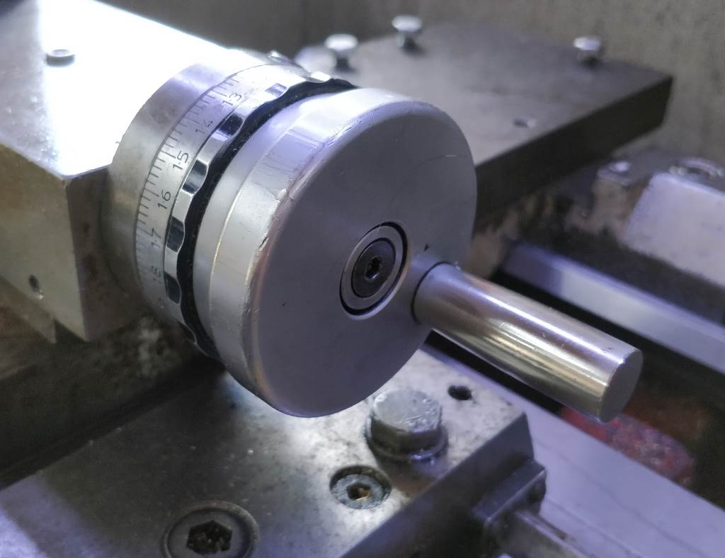
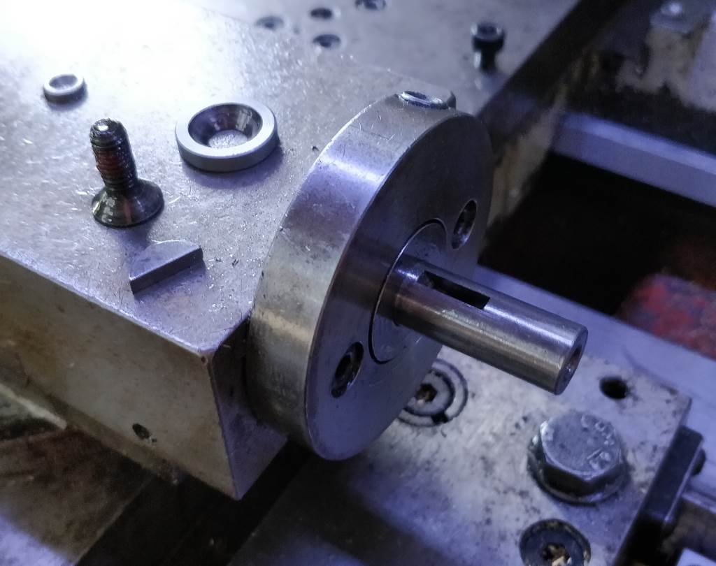
These two photos show the way the hand-wheel is mounted on the M250. The parts shown in the right-hand photo are used to mount the female dog.
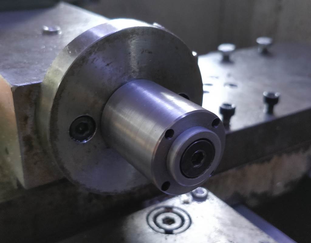

The left-hand photo shows the female dog fitted. The Woodruff key is used to engage the dog to the shaft and the same screw and washer that held the hand-wheel on are used to hold the dog in place. The only part not used is the hand-wheel itself.
The right-hand photo (which is the same as the one at the top of the page) shows the assembly fully fitted. Switching between hand-wheel and motor drive assembly only takes about a minute (mostly spent trying to stop the Woodruff key from sliding up out of the shaft!).
The top-slide motor makes it very easy for me to produce a smooth finish when making tapered cuts.
This website is free and ad-free, but costs me money to run. If you'd like to support this site, please consider making a small donation or sending me a message to let me know what you liked or found useful.
