Heat Treatment Oven Build Process
Page 7 of 35
Posted 21st December 2024
Back in my second post in this thread, I talked a bit about the four options I had for a PID controller for the oven build. What I said then was this:
Choosing a PID controller is an important decision. As I see it, I've got four options:
- Pick a basic PID controller (circa £15–20) and accept that it can't do anything fancy like controlled temperature ramps.
- Pick a fancy PID controller (circa £90) that can do temperature ramps / soaks etc.
- Pick a mid-range PID controller (perhaps £30–40?) with an RS485/Modbus input. This would work much like the basic controller, but I could potentially add an external microcontroller to send commands over RS485 and implement temperature ramps / soaks myself if I ever felt the need.
- Implement the whole lot from scratch using a microcontroller and a home-designed circuit board.
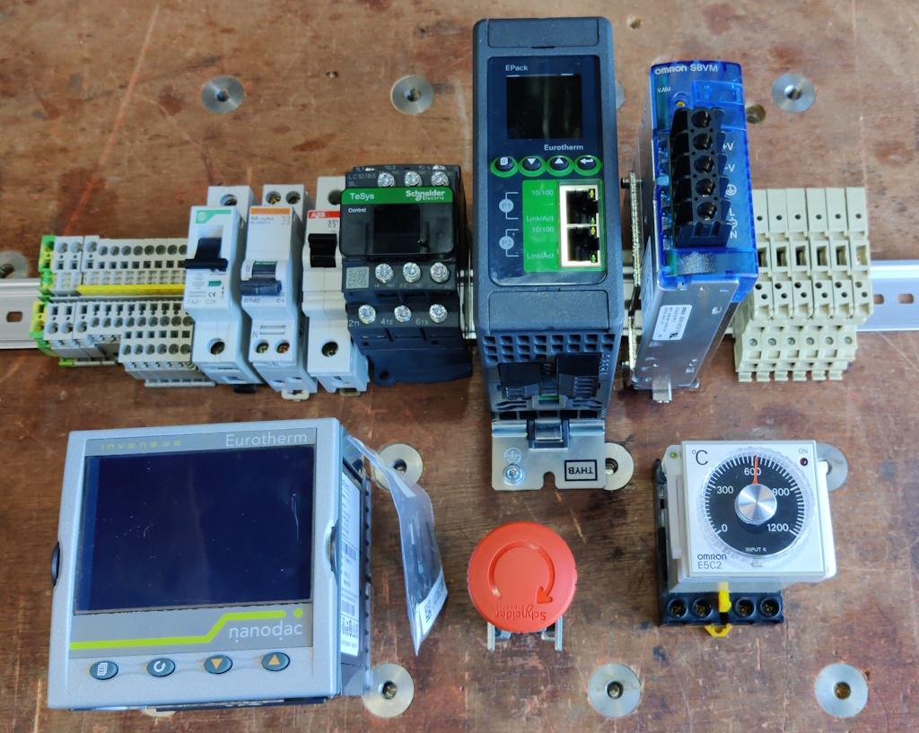
It turns out there's a fourth option that came out of the blue. An extremely generous member of the MIG welding forum read my posts about the heat treatment oven and offered to send me (free of charge) a selection of very fancy control gear for me to use in the oven. This is what came in the package he sent:
I'll talk through what all of that stuff is and does shortly, but for the impatient, there's a very, very fancy PID controller, a very fancy thyristor current controller, a contactor, a power supply, an temperature monitor, some circuit breakers, an emergency stop button and various connectors / fuse holders.
I have been completely blown away by the generosity shown (from someone I've never met).
The negative thing about this gift package (and believe me when I say this isn't a complaint!) is that my aim to document this heat treatment oven build in a way that will hopefully be helpful to others attempting the same thing will be slightly hindered in that most people won't have access to such fancy control gear. As such, I'm also going to try to write-up how I would have done it without all the posh kit!
Anyway, back to the posh-kit version of the build...
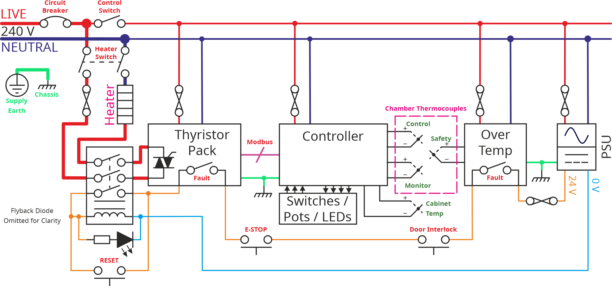
With the selection of control gear I now have available to me, I can revisit the schematic of the control cabinet (I also had a lot of help from my generous benefactor with working out the best way to do this). This is the new schematic:
While it's a bit prettier than the previous drawings I've done, I'm conscious that it's also a lot more complicated so I'm going to try to explain it bit-by-bit in the hope that it helps.
Let's look at the power circuit first, by deleting everything else from the schematic and just focusing on that bit:
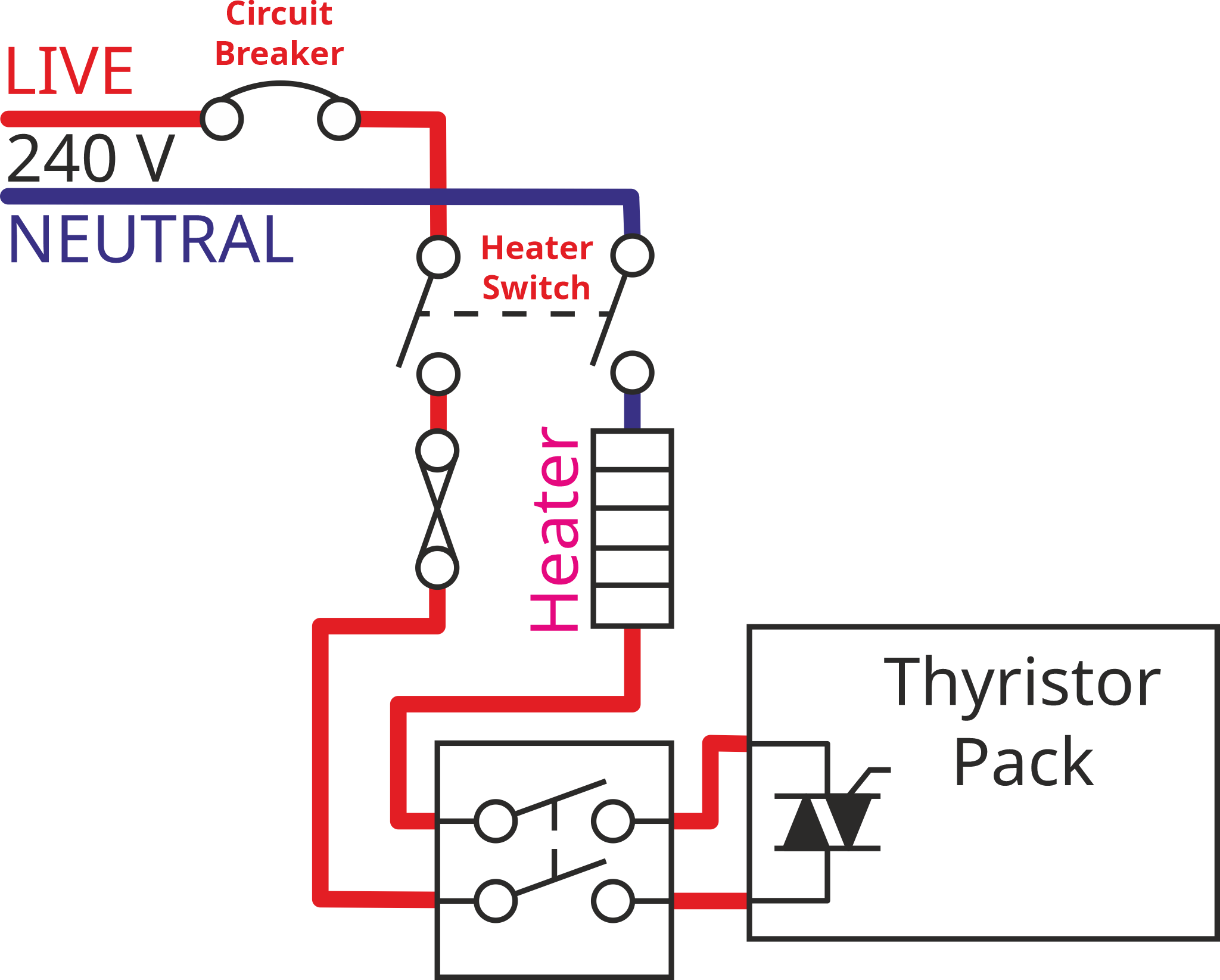
It's still a little complicated I think due to the layout being better suited to a complex diagram than this simplified version, so let's lay it out in a simpler way. Hopefully by comparing the previous image with the next one, you'll be able to see that they represent the same circuit.
The power from the mains supply first goes through a circuit breaker. That will protect the system from massive overcurrents. A little bit later in the circuit (after the heater switch) I've also added a fuse (the thing that looks like two circles joined with a cross - that's a slightly old-fashioned symbol for a fuse, but I think it's a bit prettier than the modern one that looks like a resistor with a line through it). The fuse is arguably a bit pointless with the circuit breaker there to protect things. However, I thought I'd include the fuse as an extra layer of protection and also as dedicated protection for the heating element (the circuit breaker also provides power to the control electronics).
As well as the overcurrent protection devices (circuit breaker and fuse) there are couple of linked switches in the diagram. One of these is a simple toggle switch, the other is a contactor (basically the same thing as a relay, just a bit bigger). I haven't shown the contactor coil in this diagram but you can see it if you look at the first schematic in this post.
The switch is arguably unnecessary with the contactor there; however, I quite like the idea of being able to hit a switch and know for certain that the mains connection to the heater has been removed.
The contactor is there to cut the power to the heater in the event of any fault in the system. I'll talk about that a bit more in the next post when we come onto the safety circuit. The one thing to note (from the main schematic) is that the contactor isn't a switch that the user would ever touch, the switches are closed as a result of current flowing through the contactor's coil.
Finally, there's the thyristor pack. Unlike the solid state relay (SSR) used in the simpler version of the circuit (and the version shown in the schematics in earlier posts), the thyristor pack can control the level of current (rather than just relying on the mains voltage, the heater resistance and Ohm's Law) as well as turning it on and off. This means that the heater can be run at a lower power if desired/required.
That's it for the power circuit. It looks complicated but there aren't that many components in there. In the next post, I'll talk about the safety circuit in detail and then revisit some of the other features of the design. I'll then discuss what a simpler (cheaper) version of this circuit would look like.
Page 7 of 35
This website is free and ad-free, but costs me money to run. If you'd like to support this site, please consider making a small donation or sending me a message to let me know what you liked or found useful.

 Return to main project page


