Heat Treatment Oven Build Process
Page 11 of 35
Posted 29th December 2024
I had a fairly slow start today but I've made quite a bit of progress nonetheless. The first job was to have a go at winding the heating element into a coil. On the youtube videos I've watched, they've generally done this by the very simple method of drilling two holes in a piece of wood (one tangential to the other) and using a cordless drill to turn a piece of steel bar onto which the element is wound.
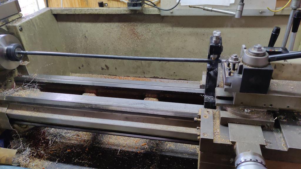
That method looks very fast and effective, but when do I ever choose fast and effective?! I thought it would be nice to do it under a little more control by turning the elements on the lathe. I was absolutely convinced I had some long lengths of 10 mm EN1A steel bar in stock, but after spending half-an-hour searching for them I gave up and got some 12 mm mild steel (I think it's S275 steel). I needed a length as long as possible and I didn't want it to be quite as big as 12 mm, so I drilled a centre hole in the end and then extended it as far out of the lathe chuck as I could (using a collet chuck as it's a bit shorter than my three-jaw chuck).
This was probably only the second or third time I'd used the travelling steady on my lathe but for a bar this length (and this far off straight: it wobbled all over the place when just supported at each end!), it was essential.
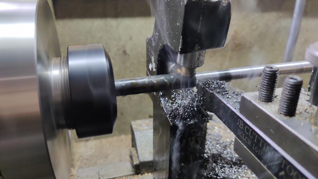
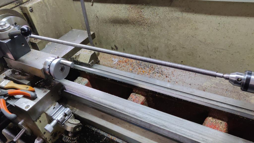
I started with a rough cut using a carbide insert tool following behind the steady. Close-up "action shot":
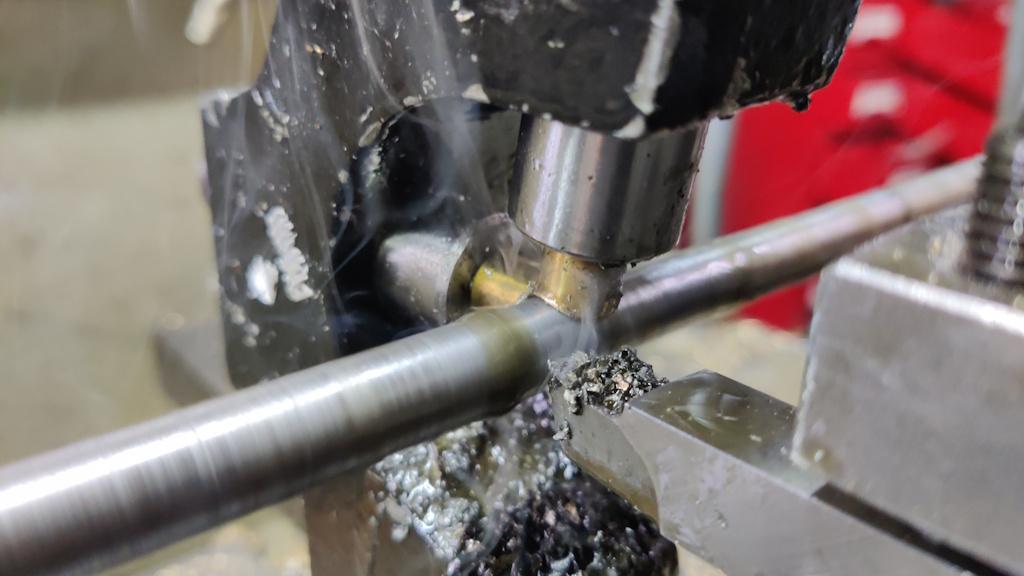
The smoke you can see is coming from the cutting oil that I applied liberally during the pass. The carbide tool left a pretty awful finish on this horrible steel, so I did a second pass using a high-speed steel tool, this time with the steady following behind (and hence riding on the finished surface):
The finish was still far from perfect (I'm sure it would have been better if I had started with a bar that was somewhere near straight), but it'll serve the purpose.
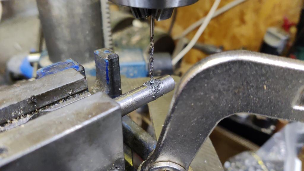
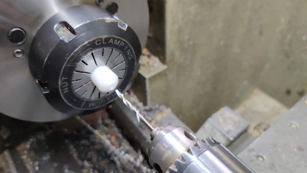
I used the pillar drill to cross drill the end of the bar with a 2 mm hole (which will hold onto the end of the element while it is wound):
To feed the element smoothly, I found a bit of plastic in the drawer and turned it down to 12 mm diameter. From how easily it cut and gave a nice finish, I think it's probably acetal. Once turned down, I drilled as deep as I could go from one end with a 1.6 mm drill bit:
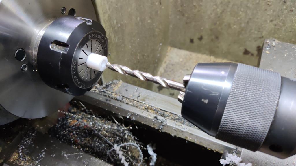
Then flipped the part round and used a (much longer) 6 mm drill bit to go deep enough to meet the end of the 1.6 mm hole:
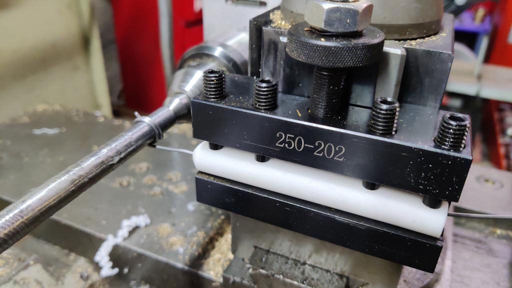
The acetal part could then be held in a tool holder and used to smoothly feed the 1.4 mm diameter wire:
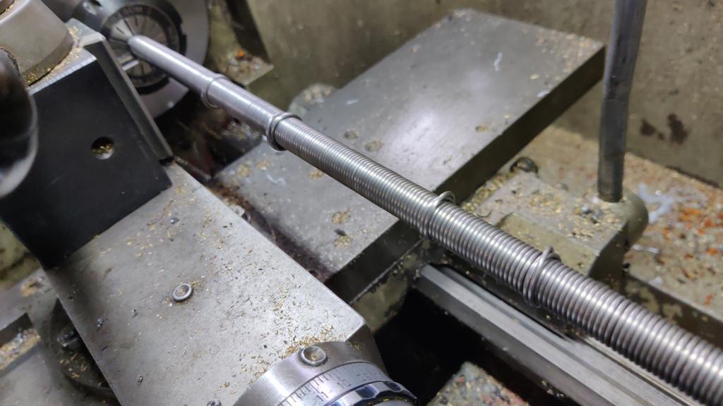
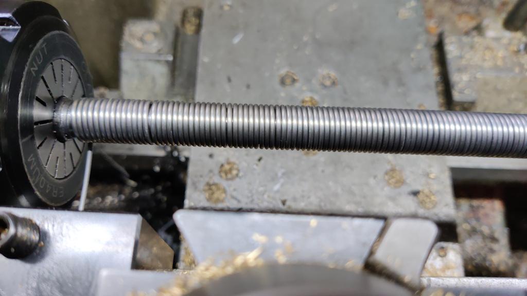
On the first go, I set the lathe up for a 1.4 mm pitch thread (so that the carriage moved 1.4 mm per turn, which should end up with the wire tightly bunched). Unfortunately, it ended up with a few lumps here and there:
I suspect that the wire is slightly over 1.4 mm diameter and hence every now and again it needed to self-correct slightly by layering up. For the second go, I changed the lathe to run on 1.5 mm pitch and it was much better:
In this case, the "corrections" for diameter/pitch mismatch were just a very small gap now and then:
Here are the two coils next to one another (after stretching them a little by hand to separate the coils):
To sort out the lumpy bits of the first coil, I placed it back on the mandrel (held in the bench vice) and manipulated it with pliers and fingers until it was looking a lot neater:
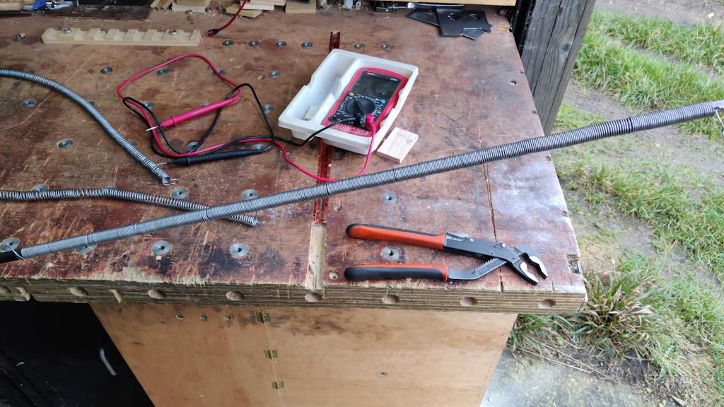
I could then do some investigation into coil sizing and position. The first coil ended up as 16 Ω; the second as 15 Ω. I've been designing the oven around a total resistance of 25 Ω or more (to suit the maximum continuous current rating of a UK three-pin plug). It's not the end of the world if it ends up more than that (as I can run it of a 16 A or 32 A plug if required as I have a suitable socket in the garage), but it'd be nice to run it off a normal plug if possible. With the two in series, the resistance will be 31 Ω; that would be fine as the current would be lower than with 25 Ω.
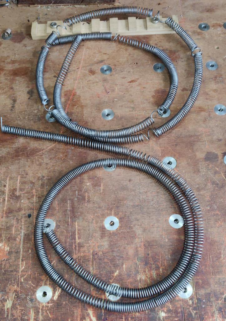
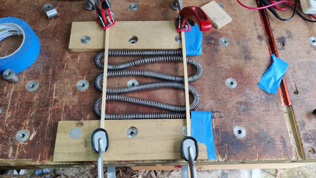
For 31 Ω I would use the two coils I've made, one in each side wall of the chamber. The size of the inside wall of the cavity with the initial brick layout is about 230 mm × 150 mm. To see what that would look like, I placed a couple of planing stops with their edges a bit under 150 mm apart. I used a pencil mark to show where the 230 mm dimension was and had a go at wrapping one of the coils back and forth in that space:
That seemed a bit dense to me: I'm not convinced I could lay that out and "mill" the slots for the the coils without the bricks breaking (as there wouldn't be much material left between the coils). If I go with this size cavity, I think I'll have to have heating elements in the side walls and the "ceiling" - that'll mean I could use coils half this length (and hence 8 Ω each) and the total would be 24 Ω, which would be close enough.
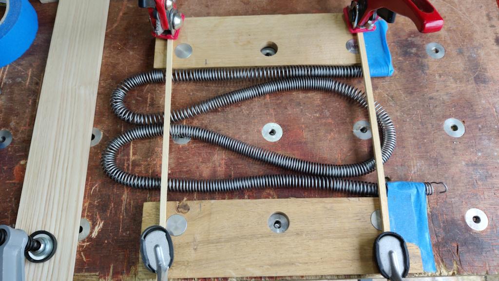
The alternative is to increase the depth of the cavity to 330 mm (by having three rows of bricks). To try that out, I clamped a piece of wood at the right distance as an end stop and had another go at the layout:
That looks a lot more comfortable to me, so I think I'll go with that one. The disadvantage is that, if I try to use this chamber for casting (with the chamber lying on its back), the crucible will need to sit on top of something (perhaps an off-cut of fire brick?) to raise it up high enough to be able to grab hold of it. I think I can live with that.
Page 11 of 35
This website is free and ad-free, but costs me money to run. If you'd like to support this site, please consider making a small donation or sending me a message to let me know what you liked or found useful.

 Return to main project page