Heat Treatment Oven Build Process
Page 13 of 35
Posted 31st December 2024
Before preparing the angle iron, I wanted to get an idea of roughly the right size for the control cabinet. The size isn't really critical (it's not going to be integrated into the chamber, so will be moved independently and hence if it's a bit oversize that's fine).
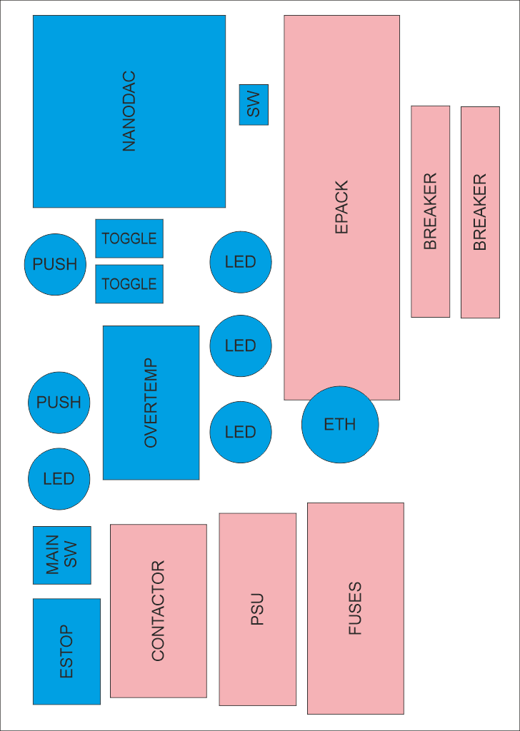
For this sort of job, I sometimes find that a simple drawing package (in this case CorelDRAW 2019) is the easiest option for playing with layouts (rather than using a fancy CAD package). I drew boxes representing the biggest dimension of each part (which won't be the same as the panel cut-out size) and played around with the layout until I found something that looked okay. I could then draw a box around it and see how big the front panel needed to be.
In that sketch, the things shaded blue will be mounted to the front of the cabinet (the cabinet door) and the things shaded pink will be mounted to the rear of the cabinet. By increasing the depth of the cabinet I could have overlapped them a lot more, but this layout gives me lots of spare space in case there's anything important I've forgotten.
I've tried to keep all the push buttons (including the emergency stop button) near the edge of the door (so they're closer to the strong angle iron rather than floating on the relatively thin sheet steel that will form the central portion). I've also tried to lay it all out relatively logically so power comes in on the right and the connections to the chamber are on the left. Thermocouple connections are on the left-hand side of the Nanodac controller, so these will be fairly close to where they come in through the side panel (but with enough slack in the cables to allow for the fact that the door will be hinged).
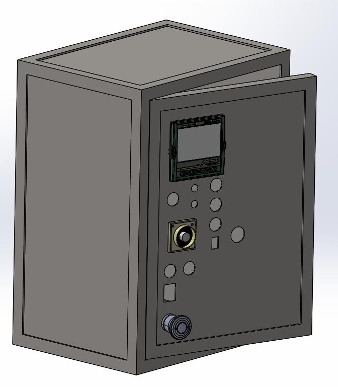
With the rough layout complete, I could quickly knock up a model of the cabinet in SolidWorks:
There are a lot of empty holes in that model as I don't have CAD models for the push buttons, LEDs, toggle switches and rocker switches I'll be using, but I do have datasheets for them, so the hole sizes should be correct. I haven't got as far as modelling the holes for thermocouple inputs, power output to the chamber, power input from the wall socket or any of the stuff that sits on the back panel, but the locations of those won't be so critical compared to the door components, so I might just figure them out as I go rather than trying to do a CAD model.
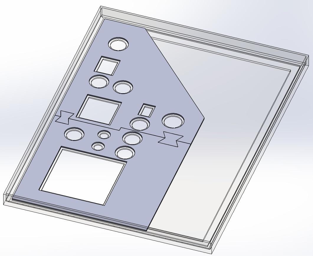
With the CAD model complete (ish), I could use the door model to create a new part (in an assembly context so I could refer to the door geometry):
This part is quite simple in that it's a 2 mm thick plate with holes that are 3 mm offset from the ones in the door. That part can be 3D-printed (in pieces, hence the butterfly joints, to allow for the limited size of the bed of my 3D printer).
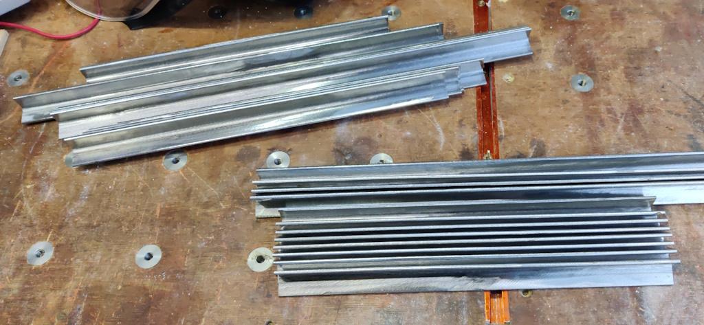
With dimensions worked out, I could get on preparing the 20 mm × 20 mm × 3 mm angle iron. In the past (e.g. see here) I've used citric acid to remove the mill scale, but it takes quite a while even in warm weather and in December is likely to take even longer. I was too impatient for that so I just used an angle grinder. I started using a "non-woven preparation wheel", which works very well, but needs a variable speed angle grinder to run it relatively slowly. My only variable speed grinder is a cordless one and it's a lot heavier than my mains one, so after preparing the first length I switched to using a 40 grit flap disc in the mains grinder instead.
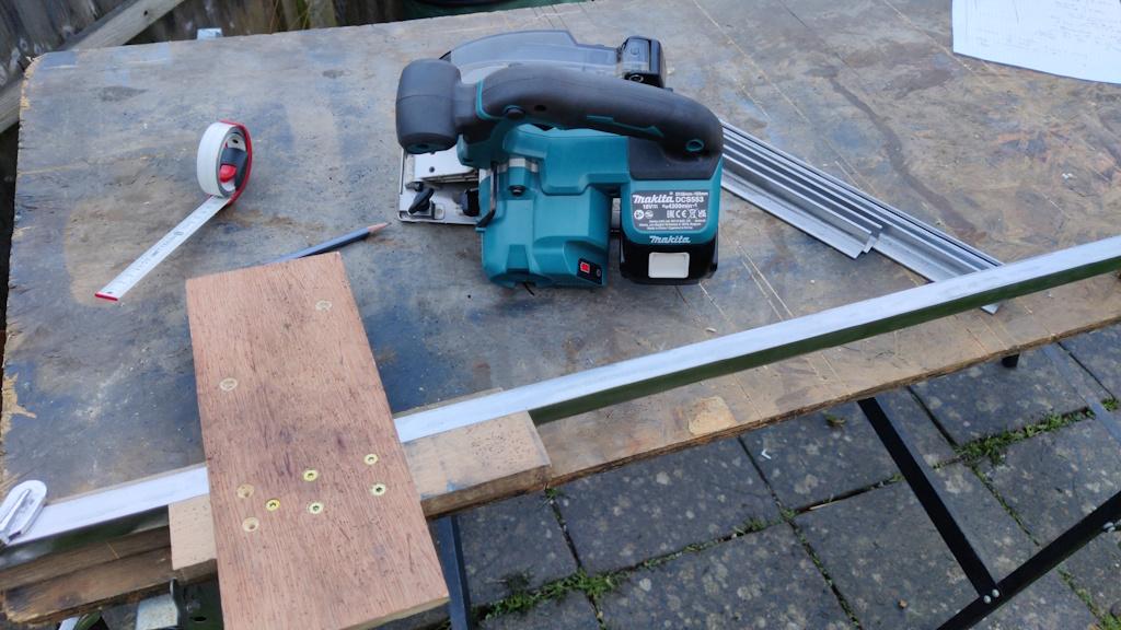
I'm sure anyone doing this professionally (where time is a bit more critical) would just clean up in the area around the welds (rather than cleaning all the mill scale off), but I find it much nicer to work with the fully cleaned steel so I got rid of all the scale. I then used my wonderful metal cutting circular saw with a simple cross-cutting jig (which had its fence cut to length using the saw so the end of the fence can be used to align it with a mark) to cut the angle down to length for the various parts.
Believe it or not, this is about 9 metres of angle iron (comprising all the pieces for the chamber body frame and the pieces for the front, back and door of the control cabinet):
I've got 3 metres left, which I don't think will be quite enough to do the chamber door and the cabinet sides, but I've got various bits of flat bar and some wider angle so I'm sure I'll be able to figure something out.
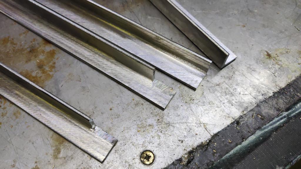
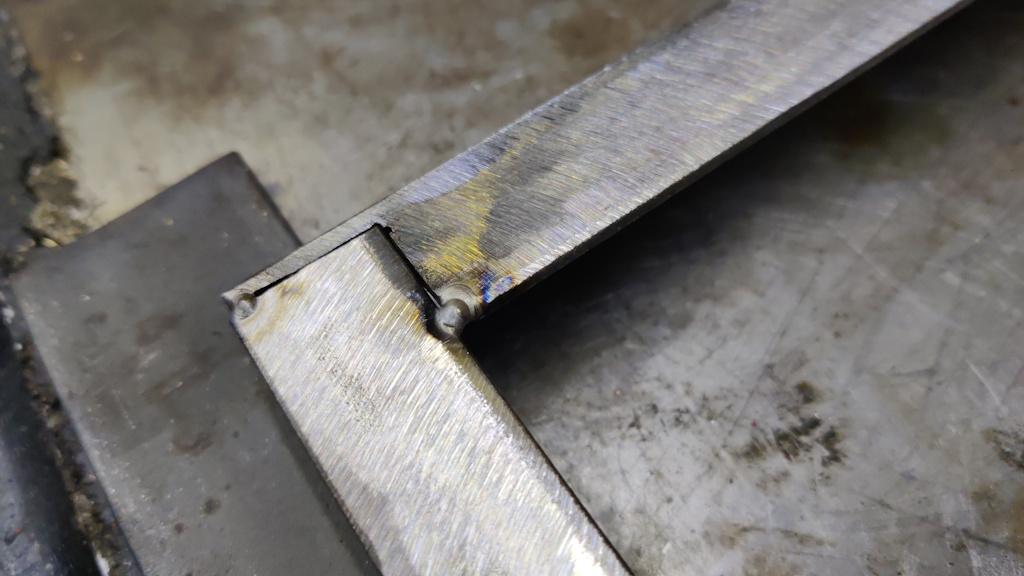
To make the angles into frames, I cut a little bit out of the corners:
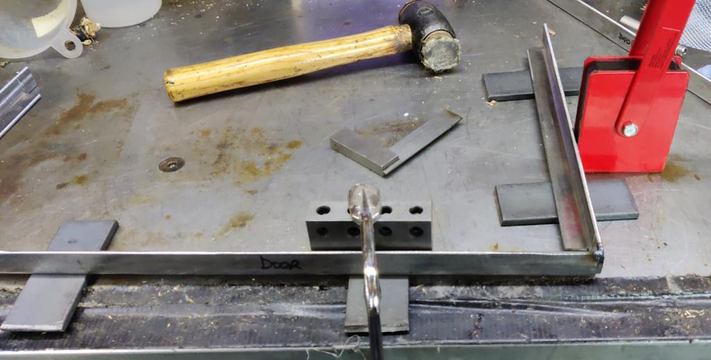
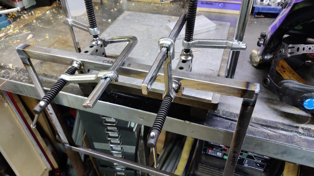
After a bit of a clean up of those corner cut-outs, I assembled the control cabinet frames, first tacking one point on one corner:
Then doing the same point on the other three corners:
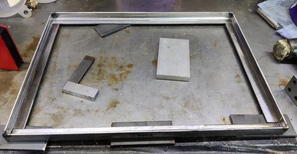
After checking that the frame was square, I tacked together the other two frames for the control cabinet and could then check that the door frame fits inside the outer frame:
Each frame then got a couple of extra tack welds in each corner and then I checked for square again:
Finally, I could weld three seams together, which should be enough I think:
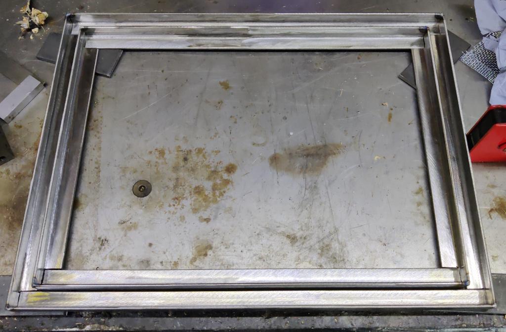
The door no longer fits in the aperture because of how the weld beads stick up, but that'll get sorted when I grind the beads back.
For the inserts inside the door, I've got a couple of sheets of 1.2 mm thick steel that has been sitting in my shed. Unfortunately, the steel has suffered a bit from the less-than-ideal storage conditions and is rather rusty. One piece was mostly covered in plastic and seems a lot better, but I thought I'd start with the rusty one and see how it goes. Hopefully the rust can be cleaned up with a wire brush or flap disc; I'll probably have to paint the cabinet before final assembly to protect it for when its in storage (I hate painting).
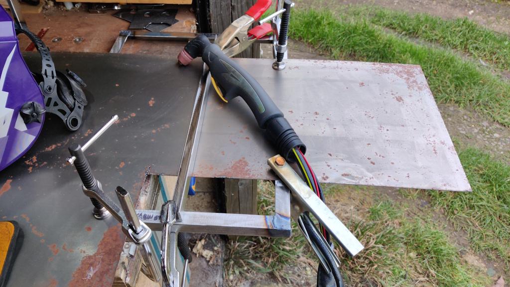
To cut the sheet up, I used one of the frames to support the sheet as it hung over the end of my bench and then used a piece of angle iron as a straight edge. I could then use the plasma cutter to split off the door insert:
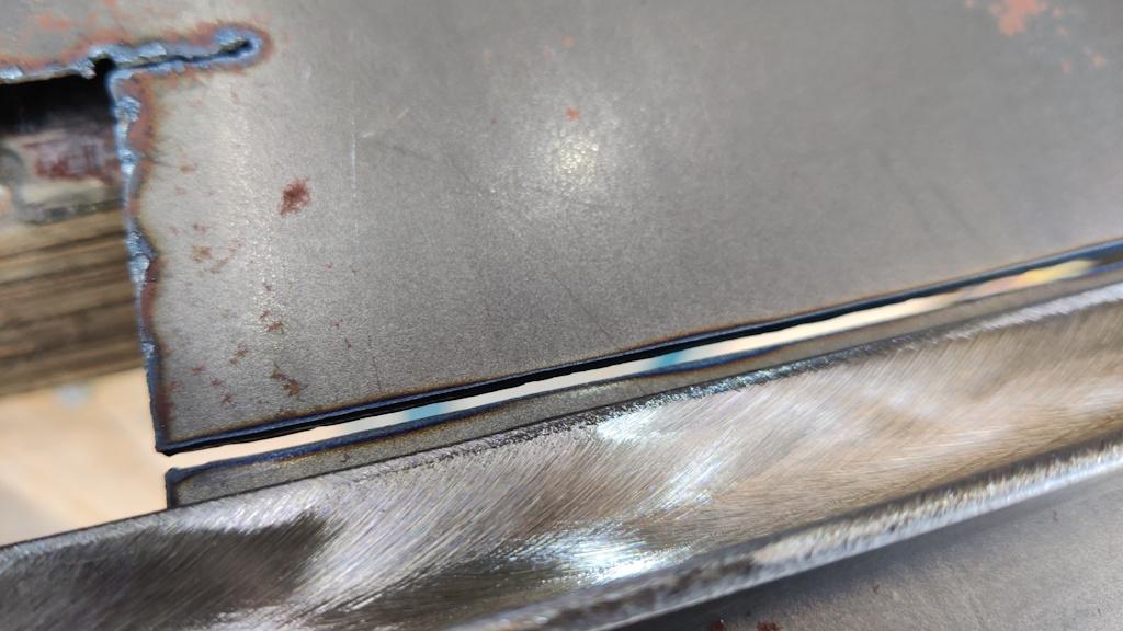
I tend to use my metal-cutting circular saw for straight cuts like this as it's fast and leaves a nice finish, but the plasma cutter is quieter and I was planning to use it for some curved and internal cuts so I figured I could use it for the straight cuts too. It left a reasonably nice finish (and only took a couple of seconds to do the 300 mm long cut):
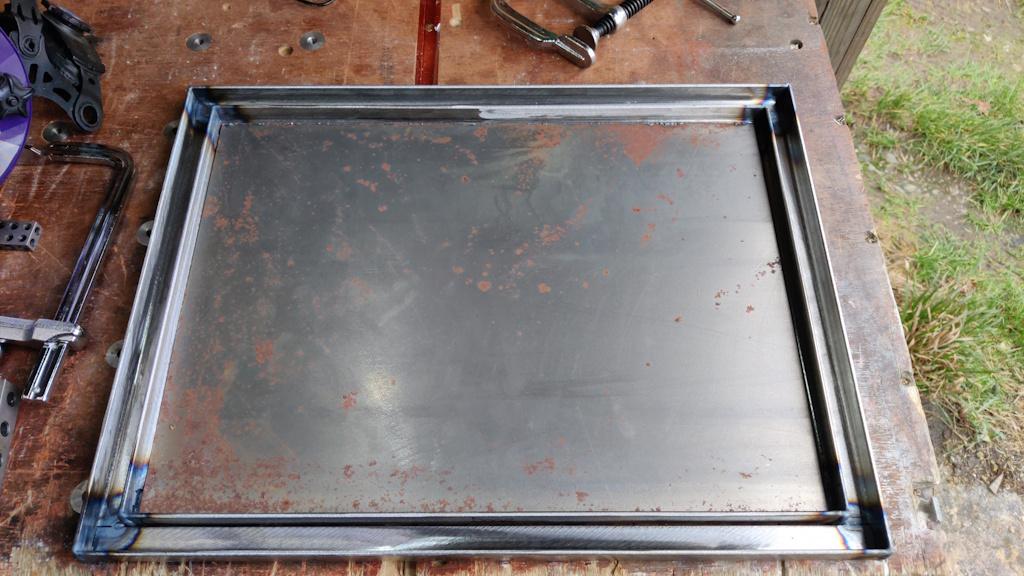
The rusty panel fits inside the door with a few millimetres of gap all the way round. Once it's fully prepared (with the rust sorted out and the holes for the control gear cut in it), the plan is to put a few short welds around the perimeter to hold it in place.
The nice thing about using this rusty bit of steel is that it means I've got more available for practice. If I make a mess of anything on the first go, I won't mind chucking this piece away and cutting some more out. If it takes more than about three goes to get it right, I'll have to break into the supply of non-rusty steel and that'll make everything easier later!
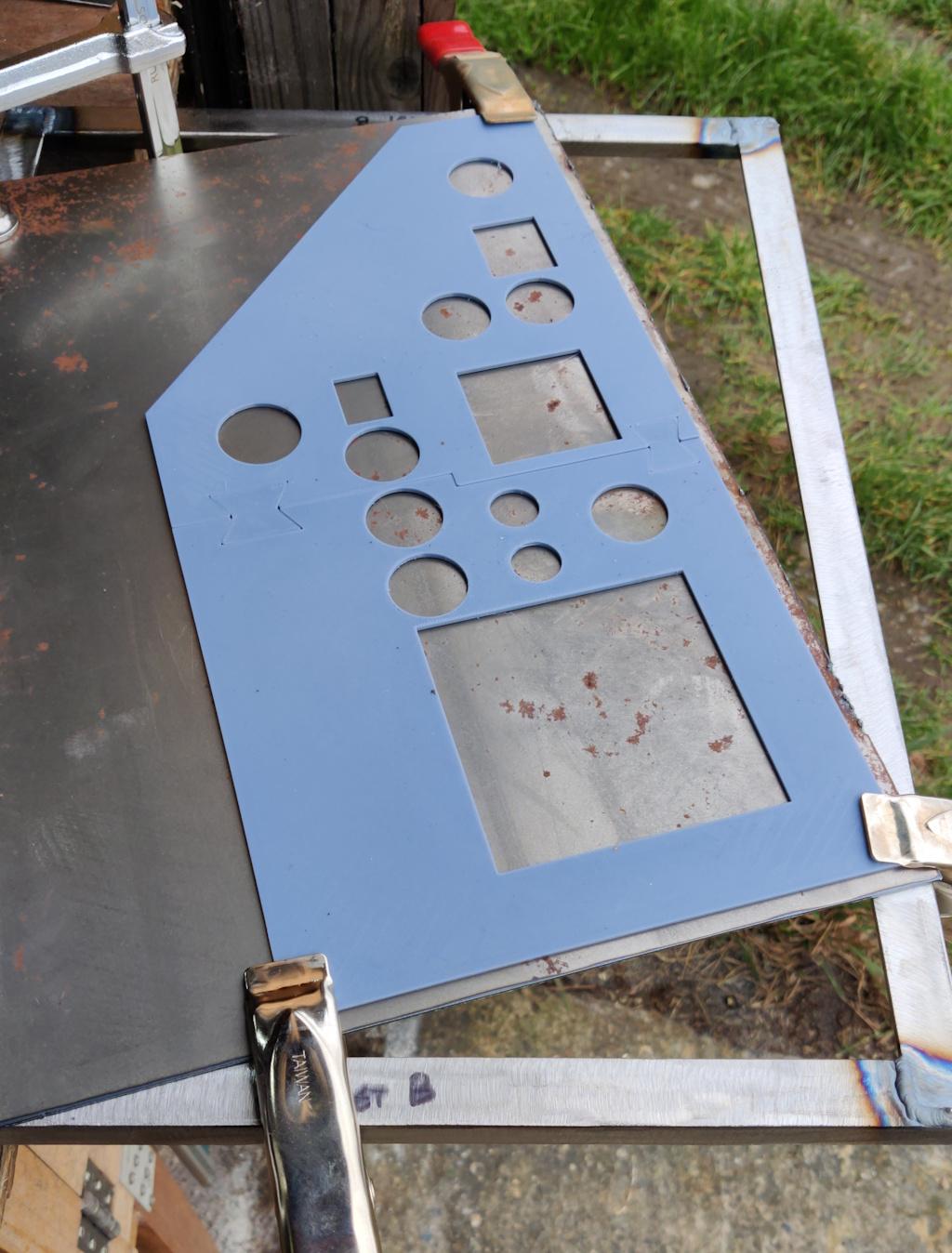
That plasma cutting template that I showed earlier had finished printing (it took about 8 hours in total) and I held it in place with a couple of clamps, using one of the frames to support the steel again so it could hang off the edge of the bench:
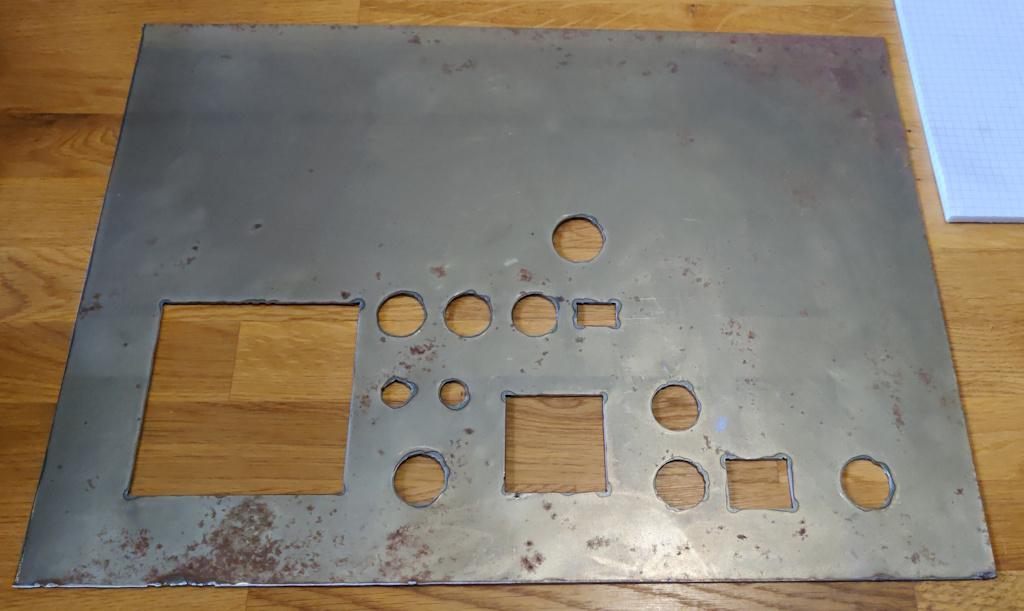
About a minute later, all the holes were cut out - the plasma cutter really is fast!
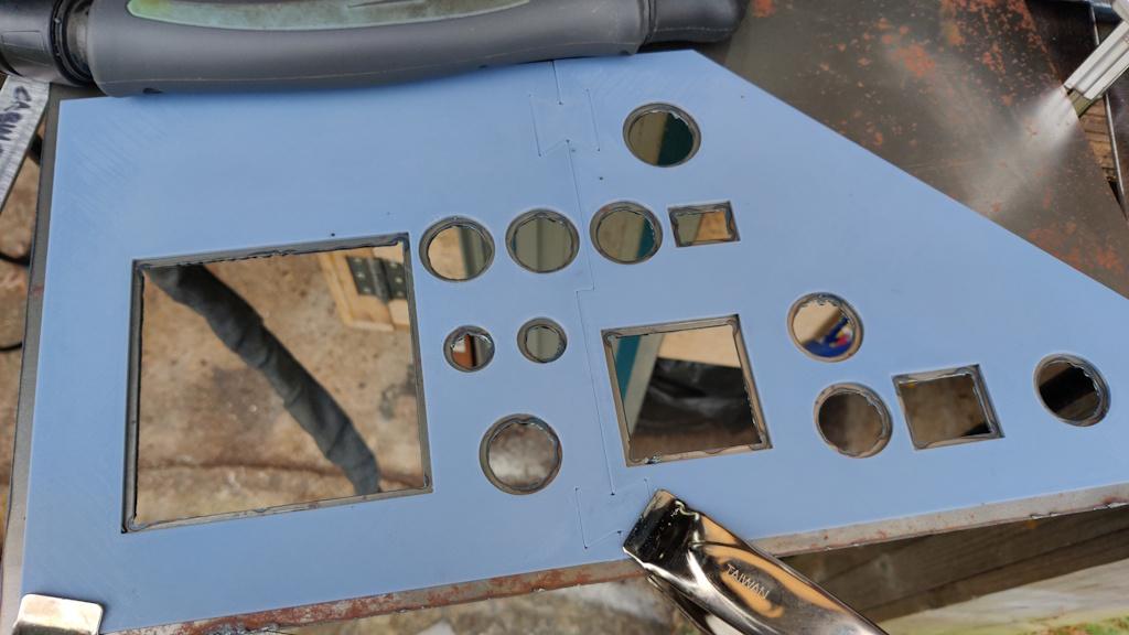
Some of the holes (especially the smaller ones for the toggle switches) are a bit shabby, but all things considered I was very happy with the finish:
I did a test fit of a few of the things that go in those holes and most were just too big to go in easily. Most would have gone in with a bit of persuasion I think, but I don't want to do that. I'm happy with that fit as I can tweak it with hand files; it won't take much filing to get them to the right size and it'll allow me to deal with some of the shabbier bits of the cut.
Page 13 of 35
This website is free and ad-free, but costs me money to run. If you'd like to support this site, please consider making a small donation or sending me a message to let me know what you liked or found useful.

 Return to main project page