Powered X-Axis Feed Mk2
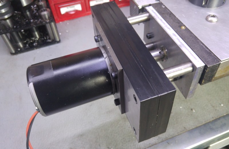
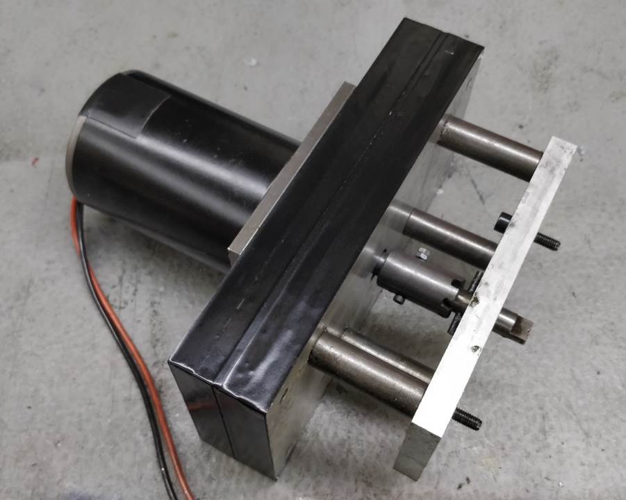
My existing X-Axis Power Feed worked well for taking finish cuts but it got very warm very quickly when removing large amounts of material and wasn't capable of running quickly when you just wanted to use it to get from one end of the table to the other. The pictures at the top of the page shows my replacement power feed, both on and off the milling machine.
It is based on a 200 W permanent-magnet brushed DC motor that was being thrown away at the end of a project at work. With 24 V applied to the motor, the no-load speed is 3600 rpm, which is way too fast for an X-Axis feed. Reducing the voltage results in a significant reduction in torque and at the sort of voltage level that would give a speed suitable for turning the lead screw, there is insufficient torque to actually turn the lead screw. To resolve this, I decided to make a gearbox to reduce the speed and increase the torque capability.
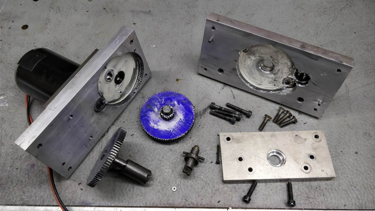
The photo above shows all the parts that make up the gearbox. The gearbox is designed around the change-gears for the mini-lathe, although I remade the gears out of aluminium using the technique's described by Mike Cox on his website. The gearbox was designed to work with two different gear ratios as I wasn't sure what would work best. In order to maintain a single tooth form (module 1) for the gears, have a two stage gearbox and keep the input and output centres in the same place, I designed it for either 9:1 (two 60:20 gear ratios) or 16:1 (two 80:20 gear ratios). In practice, I've found the 16:1 ratio perfect: applying 24 V to the motor produces a fast motion for getting the table from one end to the other; applying 12 V to the motor runs at a slower rate for producing a nice finish when fly-cutting.
I expect that at some point I'll add a variable speed controller to the motor (brushed DC motors are fairly easy to speed control as the speed is roughly proportional to the voltage applied), but for now I've just got a 12 V power supply and a 24 V power supply connected through some switches.
The motor is held together with what I believe are 3/16" UNF bolts. In metric terms, these are nominal 4.76 mm diameter with 0.79 mm pitch. The bolts were long enough that I could use them for mounting and the dimensions are close enough to M5 coarse (5 mm diameter, 0.8 mm pitch) that I could use an M5 nut for simplicity. The motor shaft has a 12 mm sleeve attached to it with a roll-pin to prevent relative rotation. The sleeve is keyed to match the change-gears.
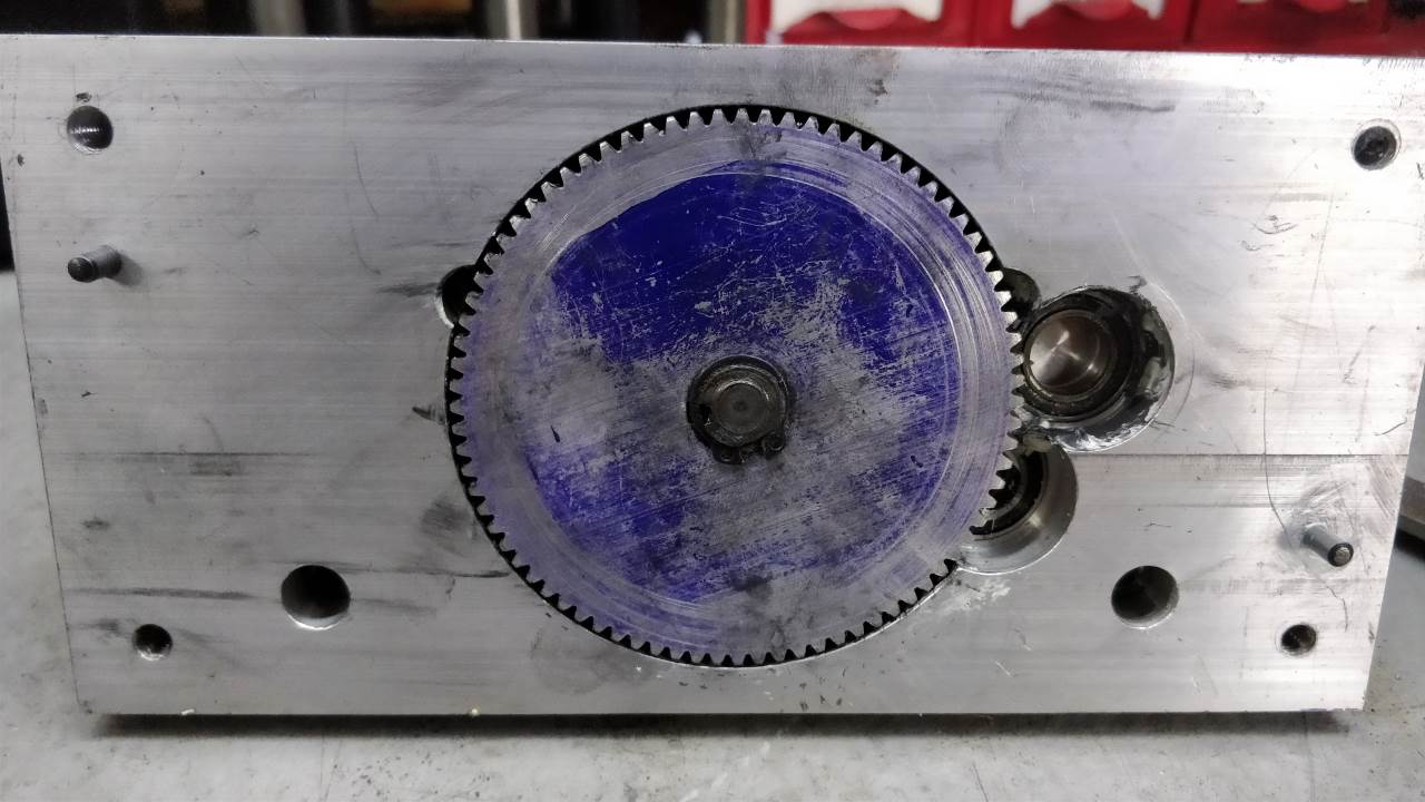
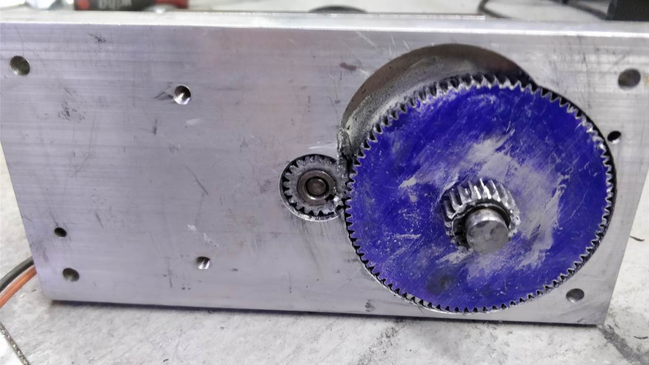
The gearbox is manufactured out of two pieces of aluminium, each 100 mm × 200 mm × 20 mm. The centres for the gears were calculated in CAD to ensure that both the 80 tooth and 60 tooth set-up could be accommodated in the same housing. The nominal spacing for the 80:20 centres was designed 50.1 mm to give a running clearance compared to the 50 mm that would be calculated for module 1 gears with these tooth counts. Similarly, the 60:20 centres are spaced as 40.1 mm. The digital read out I've fitted to the milling machine made locating these centres a trivial exercise. All shafts are 12 mm diameter with 3 mm keys to match the configuration of the mini-lathe change-gears. As you can see from the pictures, I never quite got round to removing the layout-blue that I used to mark out the gears.
The new power feed works really well and doesn't get hot even when running for very long periods. This has helped me when removing significant amounts of metal as I'm more willing to take lighter cuts and do more passes when I know I can let the motor do the hard work of moving the X-axis over and over again. I've been using it for over a year now and most big milling jobs that I've done have involved the new power feed. I'd expected the aluminium gears to suffer quite quickly (as it's generally not considered to be a very good gear material), but all the photos above were taken after a year of use and there's relatively little wear on the gears.
If I were to make it again from scratch, I'd simplify the design a bit such that the aluminium was thinner (maybe 10 mm instead of 20 mm) and only had holes bored for the bearings rather than to enclose the gears. The gears could then be enclosed by a thin strip of material around the periphery. This would make the manufacturing process significantly quicker as it took a while to bore those cut-outs for the gears. I'd also make it with only the 16:1 ratio available, which would simplify the layout significantly.
This website is free and ad-free, but costs me money to run. If you'd like to support this site, please consider making a small donation or sending me a message to let me know what you liked or found useful.

