Woodturning Lathe Build Process
Page 43 of 43
Posted 2nd May 2025
Replacing the control box for the wood lathe is something I'd been meaning to do for a long time, but I finally got round to fitting the updated version today. The previous little control box worked okay, but had a few of issues:
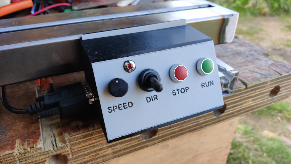
- The toggle switch for changing direction of rotation was relatively easy to knock by accident. Doing so would mean the lathe would run in reverse until I noticed that the switch had been flicked (or that the lathe was running backwards, which isn't always immediately obvious when it's spinning quite fast).
- The reversing LED (which was supposed to flash when the switch is in reverse position and help with #1) didn't work due to picking one that runs on 24 V (which is what the drive manual said was provided) but the drive actually only supplies 12 V. It's also very small, so wouldn't be especially visible even if it did work.
- The speed control was a bit limited. The variable speed drive I bought has a 5 V output for the high side of a potentiometer and an analogue input that can be used to set the speed. Unfortunately, the analogue input expects 0 to 10 V, so with the potentiometer connected to the 5 V output, I could only ever run the drive at up to half speed. I could have configured the drive so that the maximum speed was 120 Hz instead of 60 Hz or I could have added another resistor in-line with the 12 V output, but neither of them felt like a very good solution.
Out with the old...
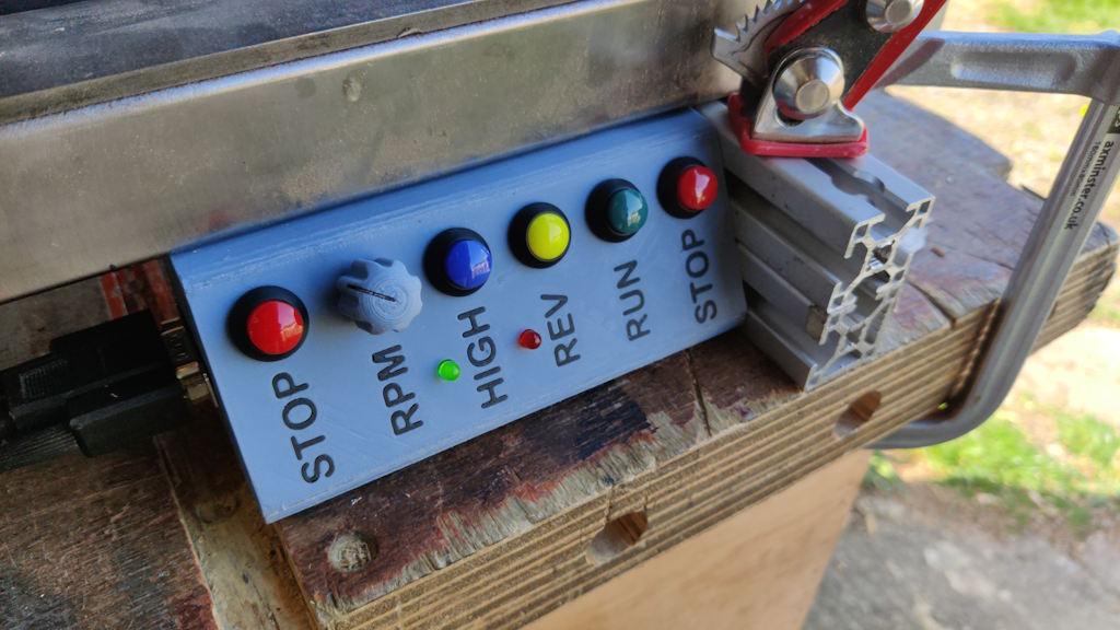
... and in with the new...
The new version has a few differences:
- The reversing LED (which flashes when in reverse mode) is bigger (5 mm diameter) and hence should be more visible. It also works, which is quite a big improvement!
- The toggle switch for changing direction has been replaced with a push switch (which has to be held down for at least 250 ms to do anything). When the lathe power is turned off and back on again, the direction will reset to forward rotation (a bit like a no-volt release circuit). The button for reverse is also slightly lower profile than the other buttons. All that should make it much less likely that I'll accidentally put the lathe in reverse.
- The control box runs entirely off the 12 V supply, with a couple of voltage regulators to generate a 5 V and 10 V internal supply. The button marked "High" switches the top end of the potentiometer between 5 V and 10 V (and turns on the new green LED when in 10 V mode). On power-up, it's connected to 5 V, so the dial gives finer control over the 0 to 50% (0 to 1800 rpm) speed range. When you press the button, it switches the potentiometer to being connected to 10 V and hence you get access to the full speed range (0 to 3600 rpm).
- I added an extra STOP button so there's one at each end of the box for easy access.
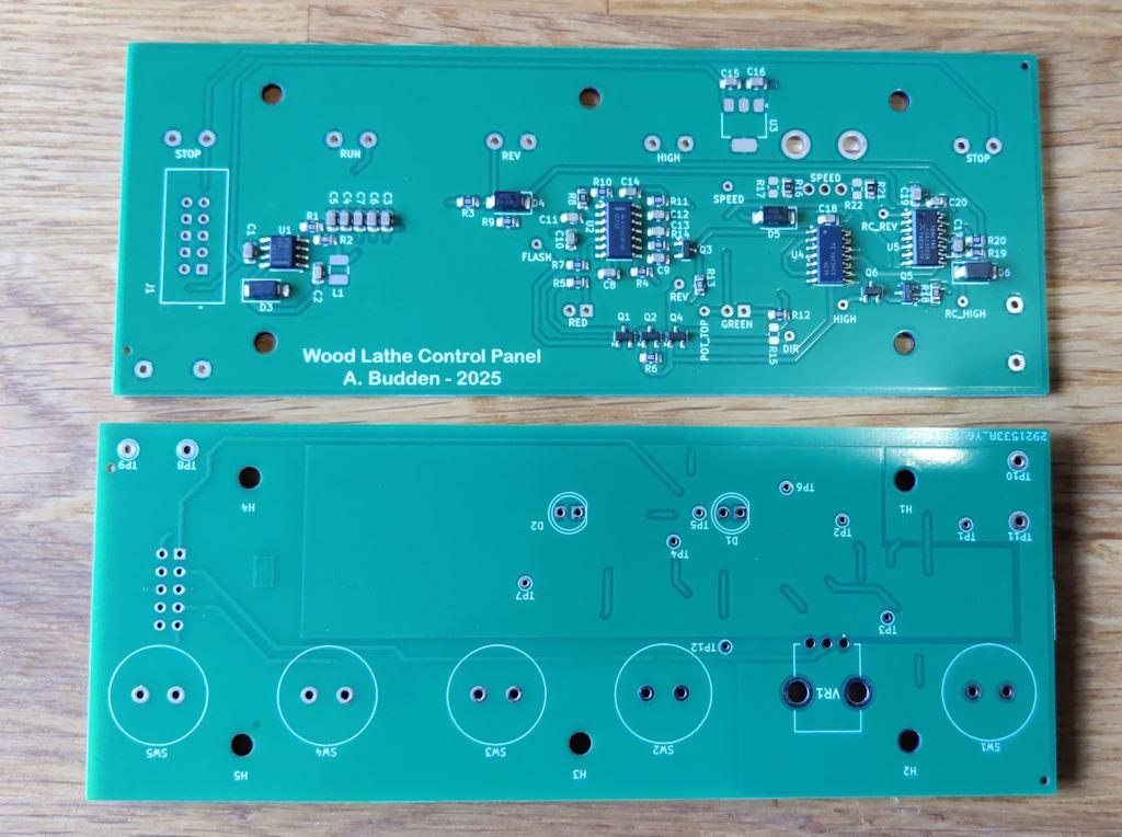
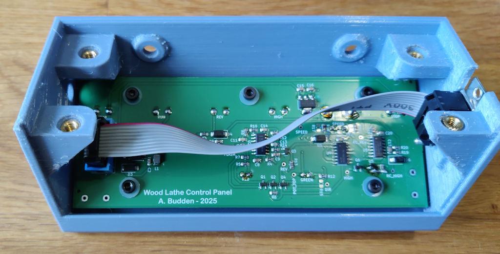
Internally, it's implemented as a PCB that's soldered directly to the push buttons and potentiometer that come through the front panel. The photo above shows the PCBs as received. I got the PCB with the surface mount components fitted from JLCPCB; the total cost (for five PCB assemblies) including PCB manufacture, surface mount assembly and shipping to the UK was only £27.40. I only need one but the minimum PCB order quantity was five and the cost difference for assembling five vs two was small enough that I figured the spares might be handy. Two of the surface mount components I picked (one of the regulators and the inductor) weren't in stock at JLCPCB, but were readily available in the UK, so I just hand-soldered them when the boards arrived. I also had to hand-solder the through-hole components, but that's quite easy to do. Unfortunately I made a small mistake on the PCB design (I somehow managed to put one of the FETs the wrong way round: it's always three-pin components that go wrong) but I was able to bodge the board by removing the component and re-mounting it upside down and at a jaunty angle and that fixed the issue. It's not ideal, but it works.
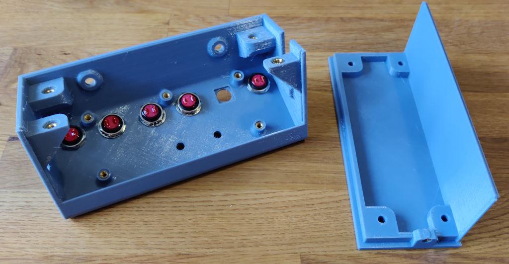
These photos show the box as-printed (with heat-set inserts inserted) and what it looks like with the PCB soldered into the box. As before, the box was 3D-printed. I used an emulated "multi-material unit" configuration (which needs a lot of tweaking, but worked okay-ish) to print the box, with about four manual filament changes inserted into the print process. That made a slightly nicer looking front panel with black filament filling in the text region rather than having debossed text with black layers as on the previous box.
The buttons, potentiometer and LEDs were hand-soldered after I'd fitted the PCB into the box.
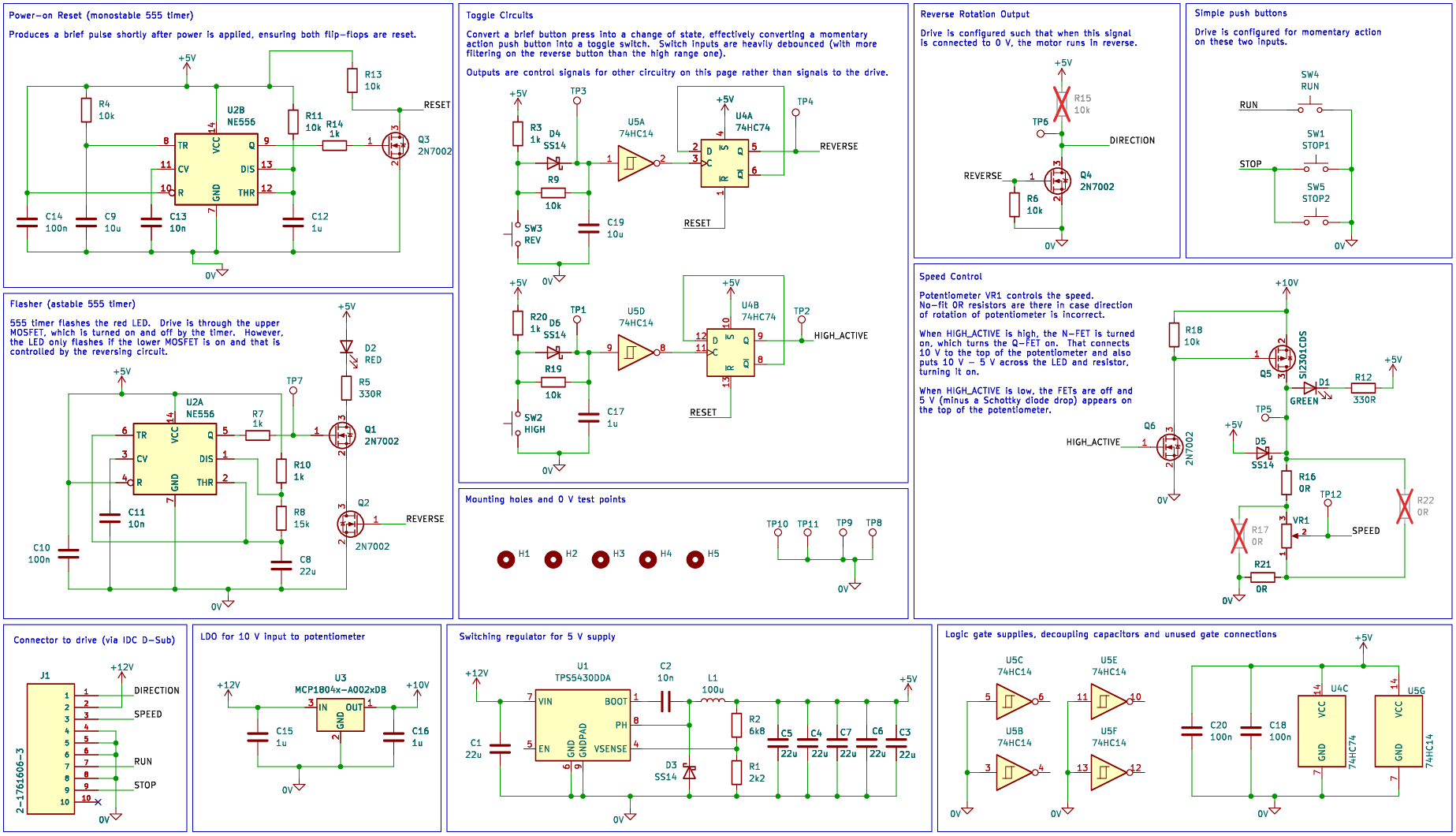
Below is the schematic (with the mistake corrected). There are some notes on the schematic, but I'm not going to go into further detail about how the circuit works; I'm happy to answer any questions that anyone has.
Page 43 of 43
This website is free and ad-free, but costs me money to run. If you'd like to support this site, please consider making a small donation or sending me a message to let me know what you liked or found useful.

 Return to main project page