Heat Treatment Oven Build Process
Page 8 of 35
Posted 22nd December 2024
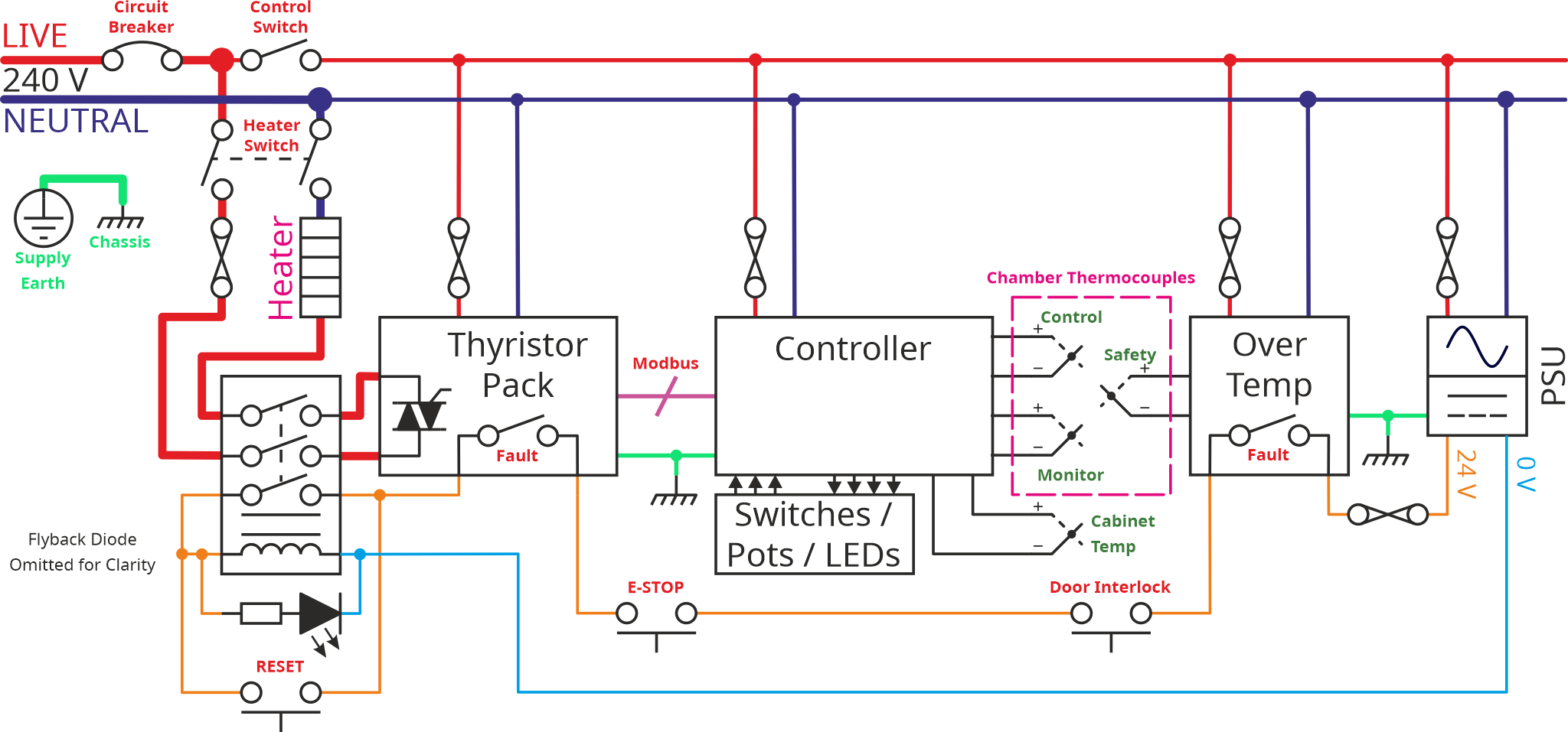
In the last post, I introduced this schematic:
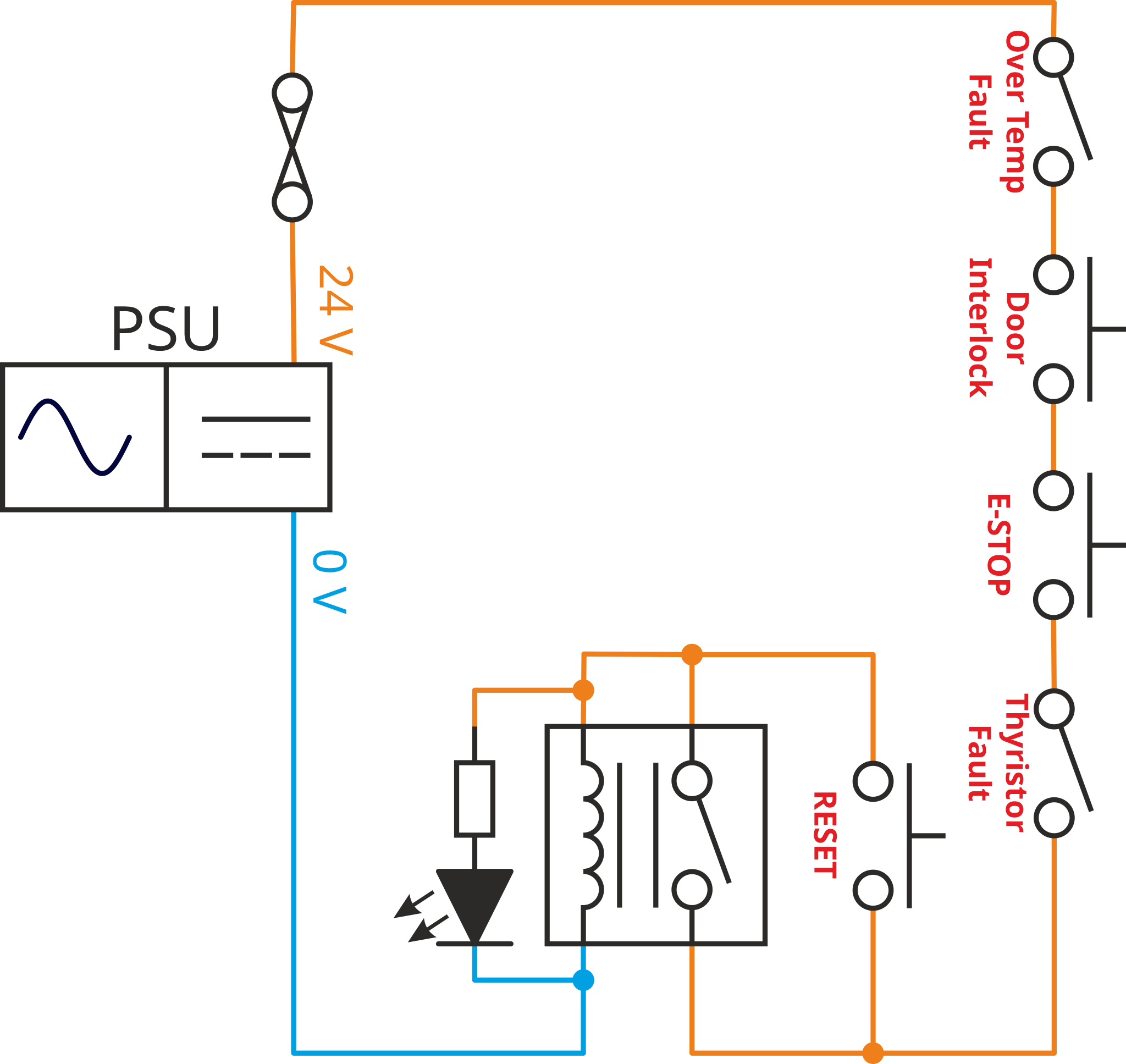
I then went on to discuss the power circuit in a bit more detail. This time I'm going to talk about the low voltage safety circuit used in the new design. If I redraw the safety circuit in an alternative layout (showing only one of the switches in the contactor), you can hopefully see that it's really quite simple:
The box with the switch, the vertical lines and the inductor (four semicircles in a line) is a contactor. Remember that the term "contactor" basically means "big relay". A relay is an electromechanical component with a coil and one or more switches. The switches are opened or closed through the application of current through the coil. The current in the coil causes it to act as an electromagnet, pulling the moving part of the switch one way or the other in order to open or close a switch. In this case, the switches are all normally-open, i.e. when current isn't flowing in the coil, the switches are open and when (sufficient) current flows in the coil, they close (and allow current to flow through the relay's switches).
The power supply produces 24 V (from a mains input); the output of the power supply is fused in case of problems. There are then a series of switches, each of which will open in the event of a problem. For now, ignore the switch marked RESET and the resistor/diode to the left of the contactor.
With those ignored components gone, the current from the power supply goes through four switches, then through one of the contacts (switches) inside the contactor, then through the coil of the contactor, then back to to the power supply.
If any of the switches open, the contactor will deenergise (as there will no longer be current flowing in the coil) and the contactor's switches will all open. Since two of the switches (not shown in the safety circuit diagram) are in the heater power circuit, the heater will be rendered safe whenever the contactor deenergises.
The reset button is there to resolve a simple problem with the circuit layout. While it's great (i.e. safe) that the contactor will be deenergised when power is initially provided to the system (as one of the contactor switches in the circuit with the coil), to turn the system on, you need to be able to bypass the switch inside the contactor. The reset push button does that: with power applied and all the other safety switches closed, press the reset button and current will flow through the coil causing the contactor to energise. The reset button can then be released (as the contactor switch will be closed, maintaining the connection).
The last part of the circuit is a resistor and LED. In practice, this will be a single component (a 24 V lamp), but I prefer to draw it showing what's happening inside that lamp. When the various safety interlocks are closed, the lamp will be on; if any of them trip, the lamp will turn off. That'll help make it obvious whether power is available to the heater.
In the next post, I'll talk a bit about the simpler version and then I'll come back to this schematic and talk about some of the complexities of all the fancy new control gear I now have.
Page 8 of 35
This website is free and ad-free, but costs me money to run. If you'd like to support this site, please consider making a small donation or sending me a message to let me know what you liked or found useful.

 Return to main project page
