Block Plane for Travel Tool Chest Build Process
Page 4 of 10
Posted 26th April 2024
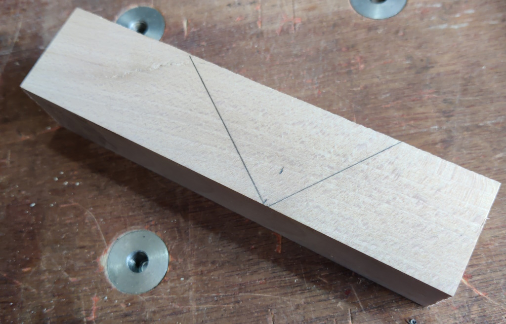
The last major part is the body. I actually started this first, working on the other parts in gaps in the body-making process. I started with a block of beech (left-over from when I made version 4, so already the right dimensions). I marked up the bed angle at 36° with a mouth at an angle 90° to that:
I'd intended to do it at 37° but only realised that much later. I don't think the difference of 1° will have the slightest effect on function, I just thought it worth mentioning the discrepancy. 37° was chosen as the equivalent angle of my Quangsheng low-angle jack plane with a 12° bed angle and 25° bevel.
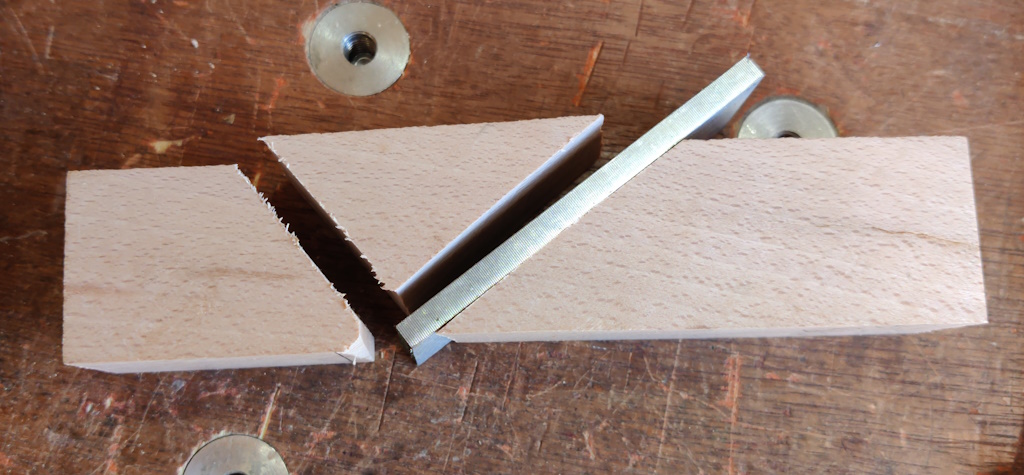
The beech block was chopped up into three pieces, one of which is scrap. My sawing was a little inaccurate and I ended up with a bit of a rounded edge on the bottom of the front piece, but that's no big deal as the bottom face of the body is going to be planed down by about 3 mm later on:
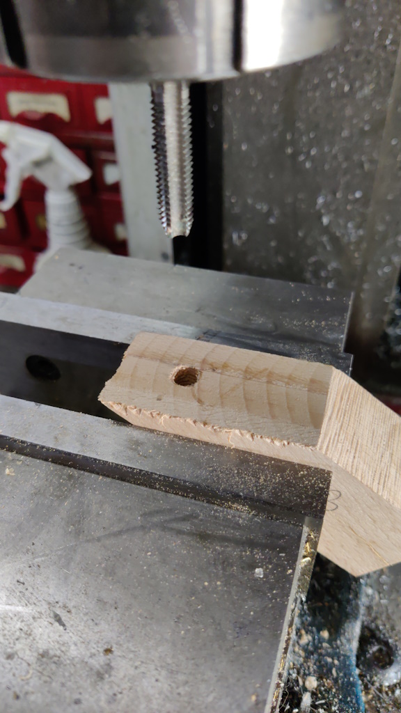
I wanted some accurate (in depth, mostly) slots and holes in the body and the most accurate tool for that sort of thing that I have is a milling machine, so I mounted the back piece in the mill vice at a 36° angle, milled the face and drilled and tapped an M8 hole:
I was a bit careless with the end mill (not choosing my travel direction correctly) and there's a bit of tear-out, but it's not the end of the world. I'll consider it a lesson for next time (if there is a next time). The depth accuracy is important as the block plane is quite thin (compared to a bench plane) and I wanted to get the holes as deep as possible (without going all the way through) for strength.
I don't really trust a tapped hole with a relatively fine pitch (1.25 mm) thread in wood, but there isn't space in such a small plane for a threaded insert without it punching through the bottom of the body. When I finally assemble the plane, the threaded rod that goes into that threaded hole will be daubed in epoxy, so the surface area provided by the thread should hopefully give a strong join and I won't be relying on the structural integrity of the threads.
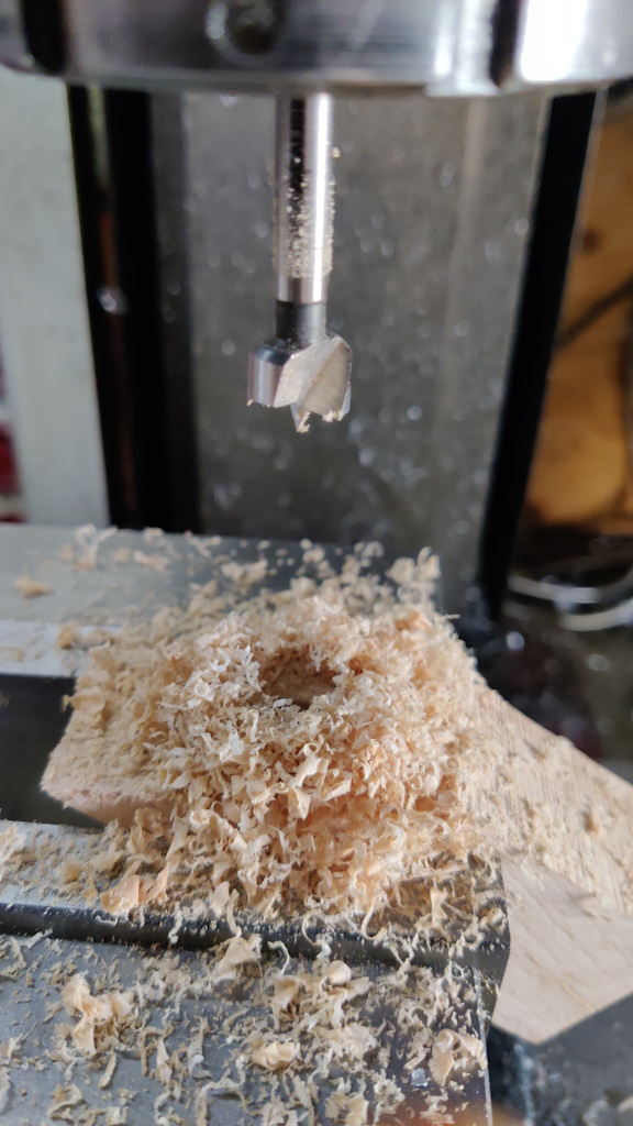
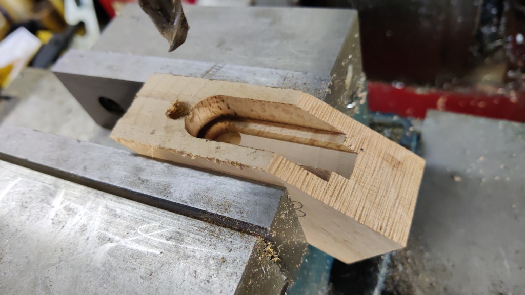
With the tapped hole done, I needed to make the space for the adjuster mechanism. I started by using a 12 mm Forstner bit to make the pocket for the brass bush in which the cam runs:
A 10 mm end mill was used to open that pocket out to give clearance for the adjuster screw and I then used an 18 mm end mill to make the pocket for the cam body and to open that out into a slot to give the rest of the space of the adjuster. I was a bit slow switching from plunging the end mill to moving the X-axis to cut the slot and that resulted in a bit of burning of the beech. I'll probably try and clean it up a bit later, but it shouldn't cause any problems if I don't:
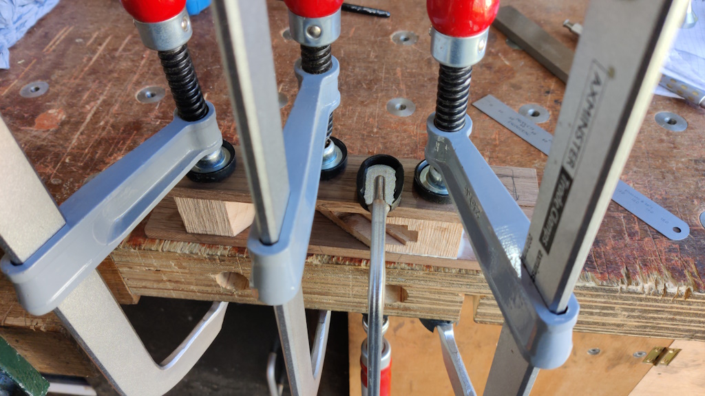
The sides of the body were made from a bit of American Black Walnut. I planed the sides to give an even thickness, then cut a couple of slices off. I decided to do the glue-up in two stages, firstly gluing the two beech body parts to one side, using a mill parallel as a flat surface to hold the two body bases in line with one another:
Once that glue had been left for a few hours, I glued the other side in place:
Page 4 of 10
This website is free and ad-free, but costs me money to run. If you'd like to support this site, please consider making a small donation or sending me a message to let me know what you liked or found useful.

 Return to main project page