Block Plane for Travel Tool Chest Build Process
Page 6 of 10
Posted 27th April 2024
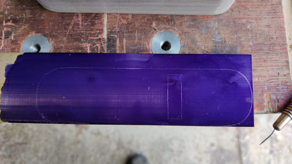
Despite England having left the Victorian Era a little while ago, it's still quite difficult to buy brass flat bar in metric sizes. The lever cap (which was made from 5 mm × 30 mm brass bar) stock came from China and was an unknown grade of brass, but I wanted the base to be made out of CZ121, to match some other bits of brass I'll be making in the next post. Without being able to buy metric sized bar, I went for some 3.2 mm × 50.8 mm (1/8" by 2") flat bar. I "painted" it in marking blue and, after plonking the body on top, I marked the shape with a scriber:
The marked-up brass bar:
It was this marking exercise that was the reason for making the wooden part of the body full depth. The slot should match the expected size on the bottom face of the plane. If I had made the wooden body in its final depth, then the slot would have opened up more (due to the angle of the blade-mounting face) and the size of the slot would be harder to gauge.
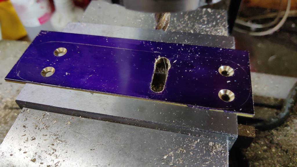
The brass bar was mounted in the mill vice and four holes drilled and countersunk. A slot was then milled with an 8 mm centre-cutting end mill:
A smaller (4 mm) end mill was then used to take a bit more material away in the corners to save filing effort later:
The shape was then roughly bandsawed out:
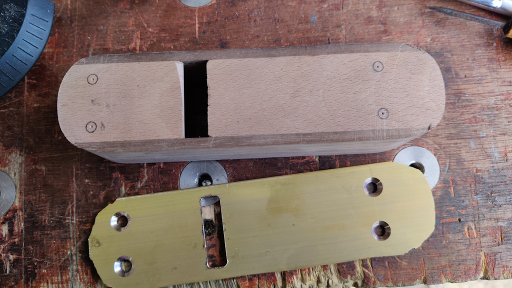
After cleaning the marking blue off with acetone, the base was placed on top of the body and the hole locations marked for pilot holes to be drilled:
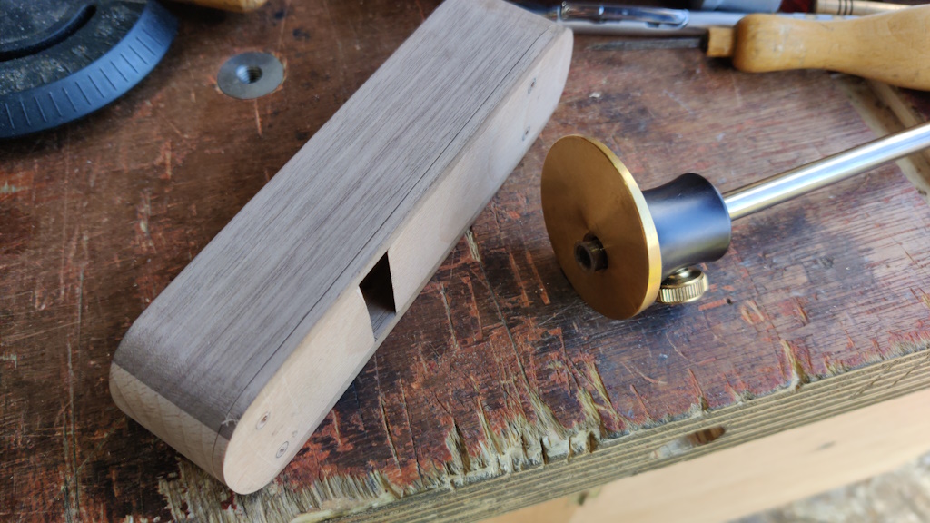
With the pilot holes drilled, a marking gauge could be used to mark the amount that needed to be removed from the bottom of the body to make space for the brass base:
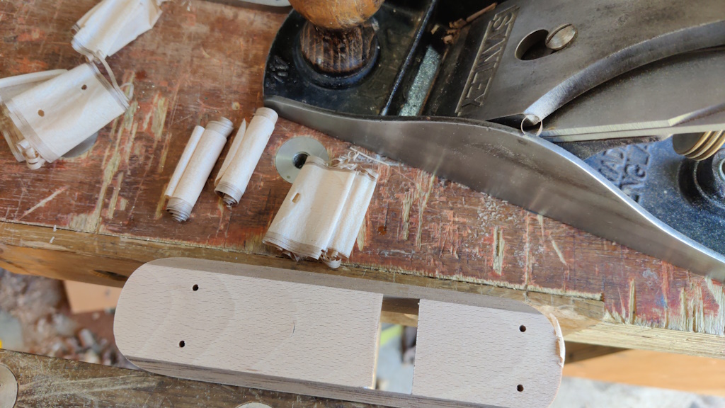
My Stanley #4½ made light work reducing the depth of the body, making some funky shavings in the process:
The planing operation exposed the bottom of the cam hole. I was expecting that: I'd deliberately drilled that hole as deep as I thought I could get away with given the depth of the plane. A small slot will be needed in the brass plate to allow for the end of the cam bush, but that's not a big deal. Sorry for the blurriness of this photo:
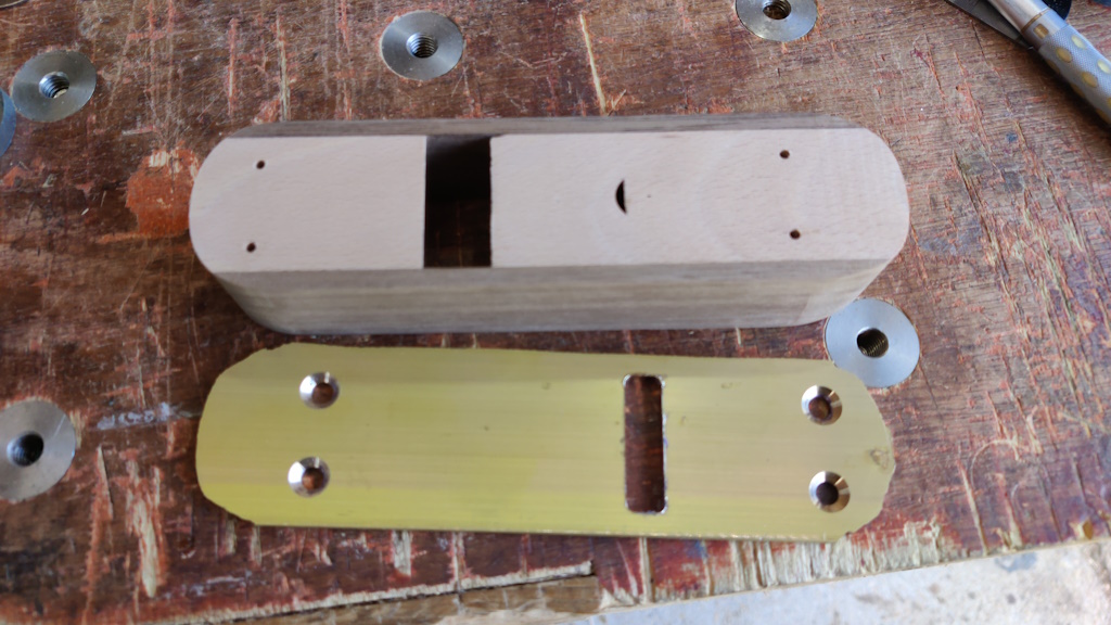
The following photo shows the reduced-thickness body sitting on top of the base. The discrepancy between the two slot sizes is (hopefully) obvious and this shows why I wanted to mark up the brass bar from the full thickness body. The right-hand end of the slot will eventually be filed to match the taper angle of the blade-mounting face of the body:
Page 6 of 10
This website is free and ad-free, but costs me money to run. If you'd like to support this site, please consider making a small donation or sending me a message to let me know what you liked or found useful.

 Return to main project page
