Travel Tool Chest & Workbench Build Process
Page 127 of 144
Posted 28th January 2024
If you've come here hoping to read about woodwork, please look away now.
I've tried to document everything involved in this tool chest project in detail. In that spirit, I thought one or two people might possibly be interested in the process of preparing the models for the 3D-printed drawer liners. If that interests you, read on...
The router plane drawer is by far the most complicated one as it involves the third dimension in terms of tool placement as well as tool shape. That design is mostly complete, although a few tweaks are outstanding. It would take me a very long time to describe everything involved in designing that one, so I thought I'd document one of the others. The saw drawer is probably the next most complicated as the saws aren't a simple shape (compared to an engineer's square or a sliding bevel or whatever).
The one thing that makes the saw drawer relatively simple is that there aren't many tools going into the drawer, so it seems to me an ideal candidate for a write-up.
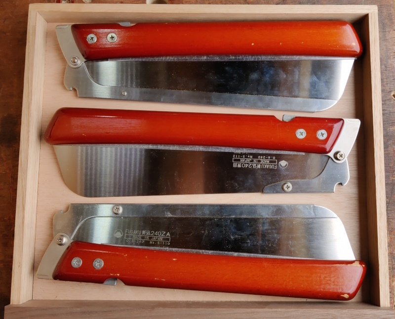
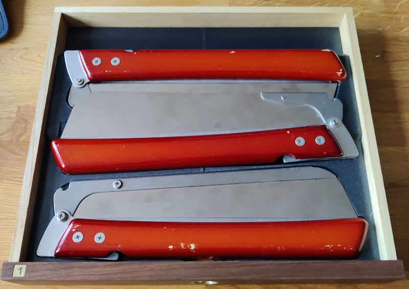
As a quick refresher, this is the drawer with the saws that I want to include:
Just to make things a bit more complicated, I'm going to overlap two of the saws. Despite the overlap, I'd like the saws to stay put during ferry crossings without them banging against one another too much. In practice, I'm sure the saws would be fine if they did bang into each other, but I'm going to protect them anyway.
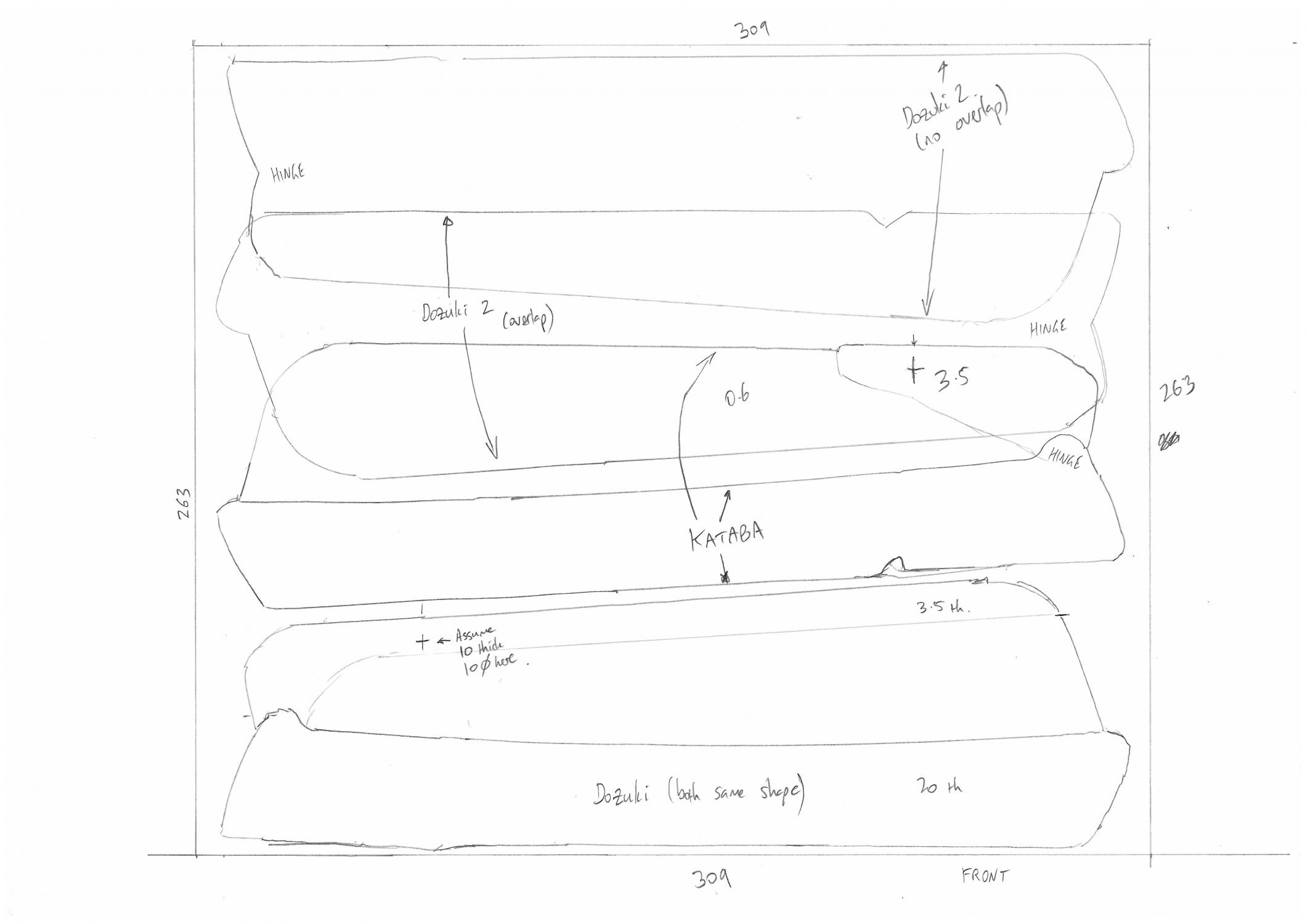
The first thing I did for this drawer was to get a sheet of (A3) paper and draw the drawer outline. I then placed the saws onto that outline and drew carefully around them with a pencil. To get the shape of the handle, I drew around the saw first with the blade closed and then again with the blade open. The two Dozukis turned out to be the same shape, but the Kataba is subtly different.
After drawing round the Dozuki and the Kataba, I also sketched the position of the other Dozuki in two different locations – overlapping as mentioned before and separate. That was just for reference and, as you'll see later, I didn't make any use of those sketches.
Note the little crosses that correspond with the location of the blade-retention screws (which result in the blade being thicker in that area).
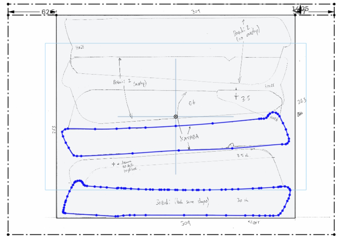
With the drawing prepared, I scanned it into the computer and loaded into OnShape. I created a new "Part Studio" and started by sketching a rectangle to match the inner size of the drawer and extruding it 1 mm thick. I then created a new sketch on the face of that base plate and inserted the scanned drawing.
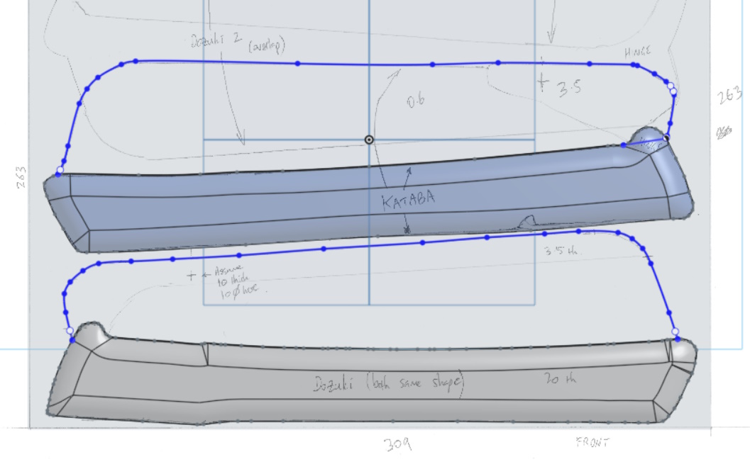
I had marked some known dimensions on the drawing, so I could scale the image until the dimensions were correct. I then used the "Spline" tool to draw around the saw handle profiles, erring on the side of being outside of the profile so that the resulting body is too large rather than too small:
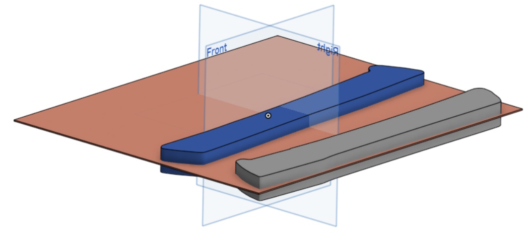
That sketch could then be extruded to the measured thickness of the saw handles (20 mm). I did the extrude operation as a symmetric one, so the initial sketch plane ended up in the middle of the handles:
I'd measured the radius of the curve on the edge of the handles using some 3D-printed radius gauges. With that number in hand (10 mm radius), I could fillet the edges of the handle:
I could then create another sketch on the same face as the previous one, this time drawing splines around the blades:
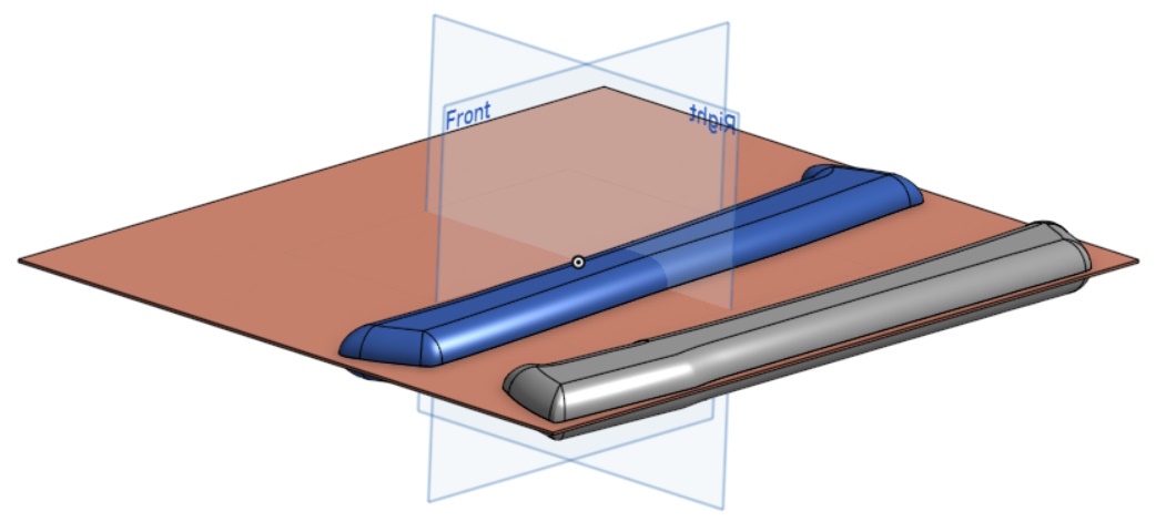
As with the previous extrude, I did a symmetric extrude again (3.5 mm this time, to correspond to the spine thickness). As both extrudes were symmetric about the same plane, the blade ended up in the middle of the body. I also created a simple sketch with just two circles, one in each of the screw locations and with the circle diameter quite a bit bigger than the screw head diameter (in case the position wasn't quite right). That got extruded as well and the end result was two models of saws and a base plate:
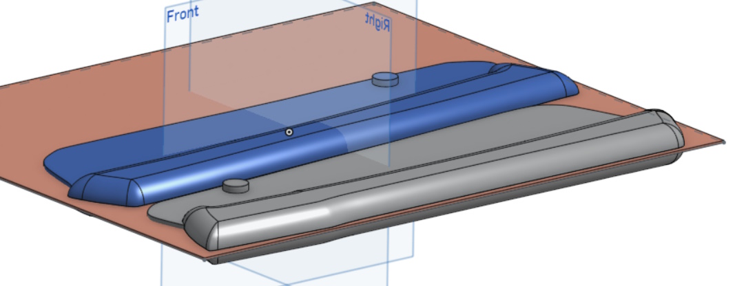
With that done, it was just a case of duplicating the Dozuki model and doing X, Y, Z and rotation transforms to drag them around until I was happy with where they sat:
The base plate was then thickened until it came half-way up each of the saws...
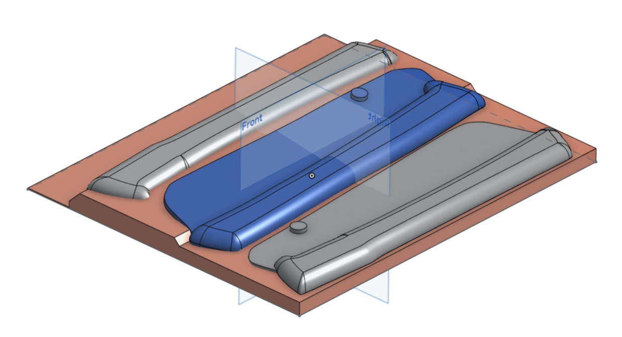
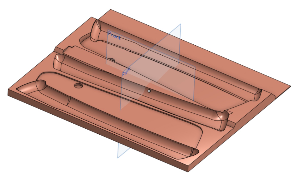
... and the shape of the saws subtracted from the base plate. A little bit of tidying up of the shape resulted in this:
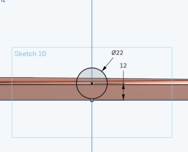
Another simple sketch was made on the front face of the model:
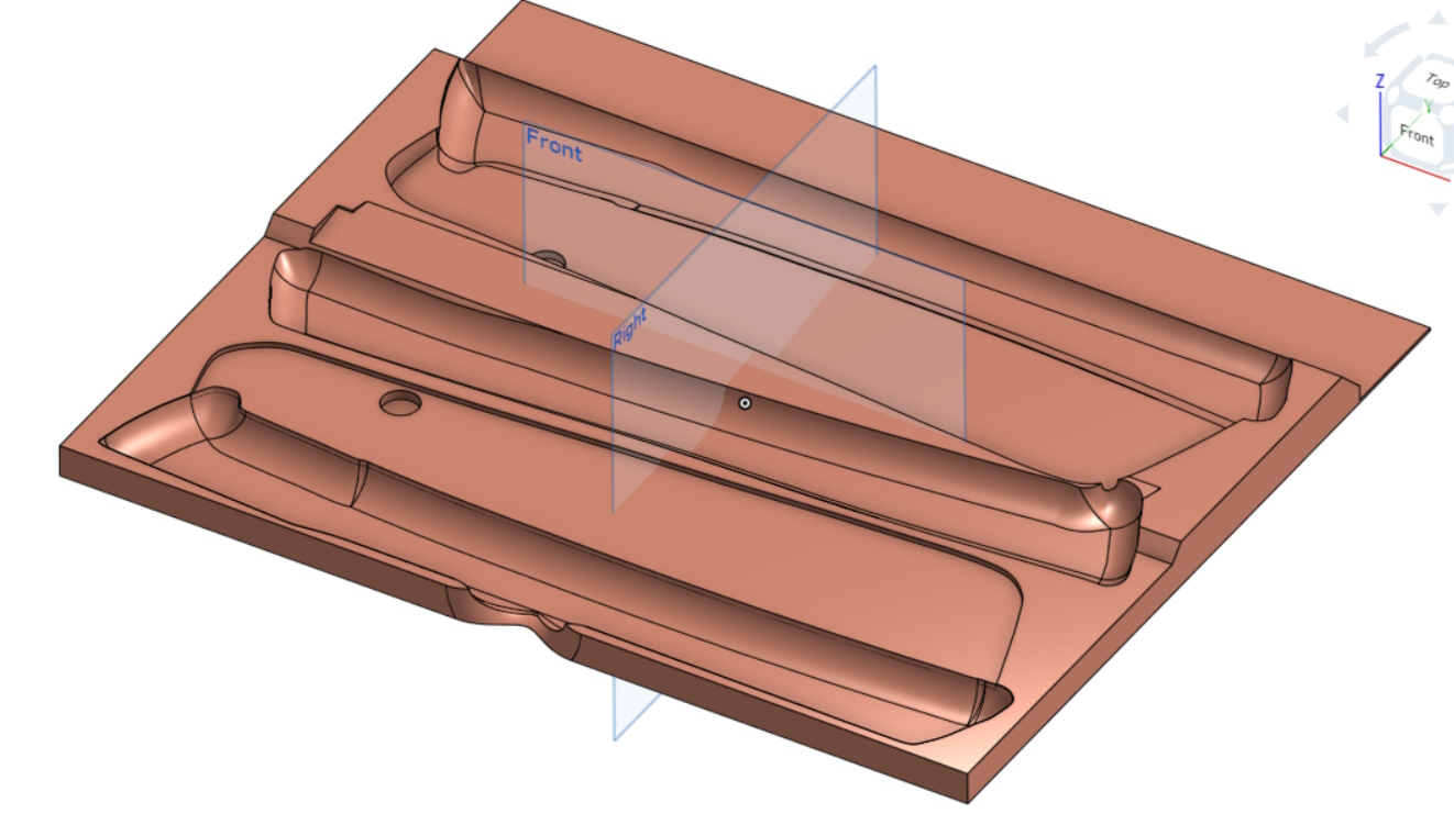
That got extruded as a cut into the front of the model and then the various edges softened using fillets.
That cut-out gives a bit of clearance behind the finger pull hole.
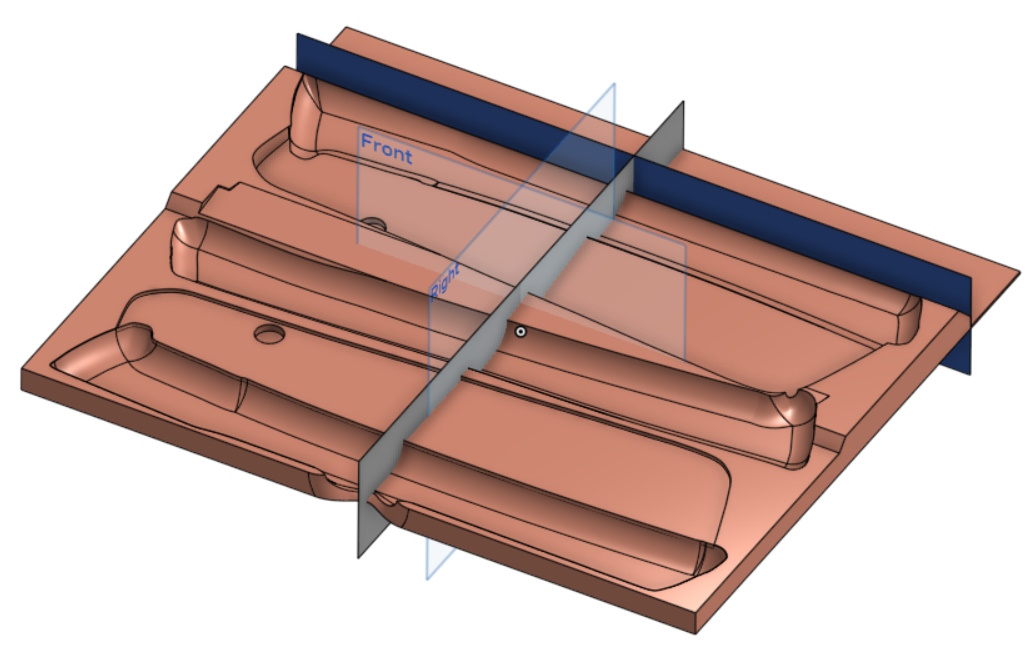
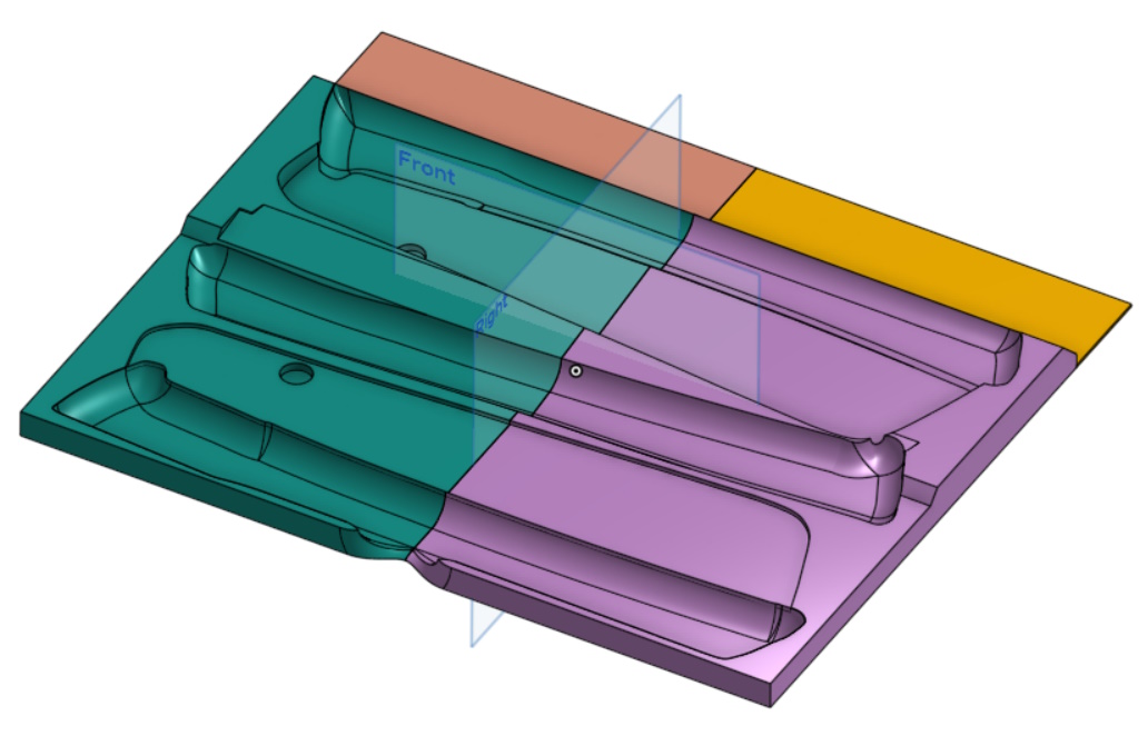
Finally, a couple of surfaces were created, each bisecting the model:
These were used to split the model into four pieces, each small enough to fit on the bed of the 3D printer.
I chose to split near the back as it means (a) that the saw body sections are in fewer pieces and (b) if I figure out something else that I want to put in that 40 mm wide section at the back of the drawer, I only have to reprint the 40 mm wide section and not half the drawer.
A little while later and the drawer is ready for use:
Page 127 of 144
This website is free and ad-free, but costs me money to run. If you'd like to support this site, please consider making a small donation or sending me a message to let me know what you liked or found useful.

 Return to main project page