Travel Tool Chest & Workbench Build Process
Page 95 of 144
Posted 16th September 2023
In the long-standing tradition of putting off decisions until the last possible moment, I've decided not to think about filling in those holes just yet. I'm sure I'll fill them with one of AndyT's suggestions, but I don't know which yet so I'll think about it later.
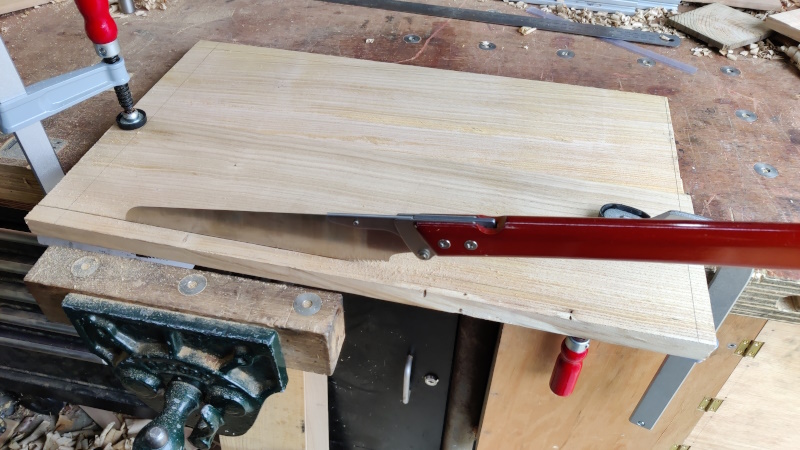
I'm back from Hong Kong now and have had a good night's sleep, so I thought I'd do a bit of gentle pottering along with the shooting board. I started by sawing along the lines (which were placed deliberately to leave the board oversize, so I could just saw directly along the lines).
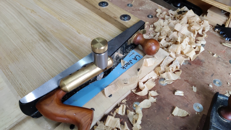
I then planed one long edge flat & square and then used it as a reference to shoot the ends to length. I find it inordinately satisfying to produce full-length end-grain shavings on a jointed panel...
Once it was a close fit end-to-end, I reduced the width of the board until it was a relatively good fit top-to-bottom:
I then took a few shavings off with the #7 until there was a couple of millimetres gap at the top: this should allow for some expansion of the panel.
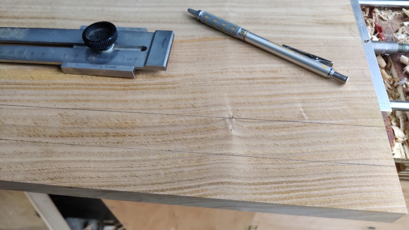
The next job was to plough a groove for the plane to run in. The idea is that, like my other shooting board, the plane will be constrained on the right so it can't drift away from the board. I measured the width of the webs on the side of the plane and they seemed to be pretty much spot on 30 mm, so I marked out for 30 mm groove, 30 mm (arbitrarily) from the edge of the panel:
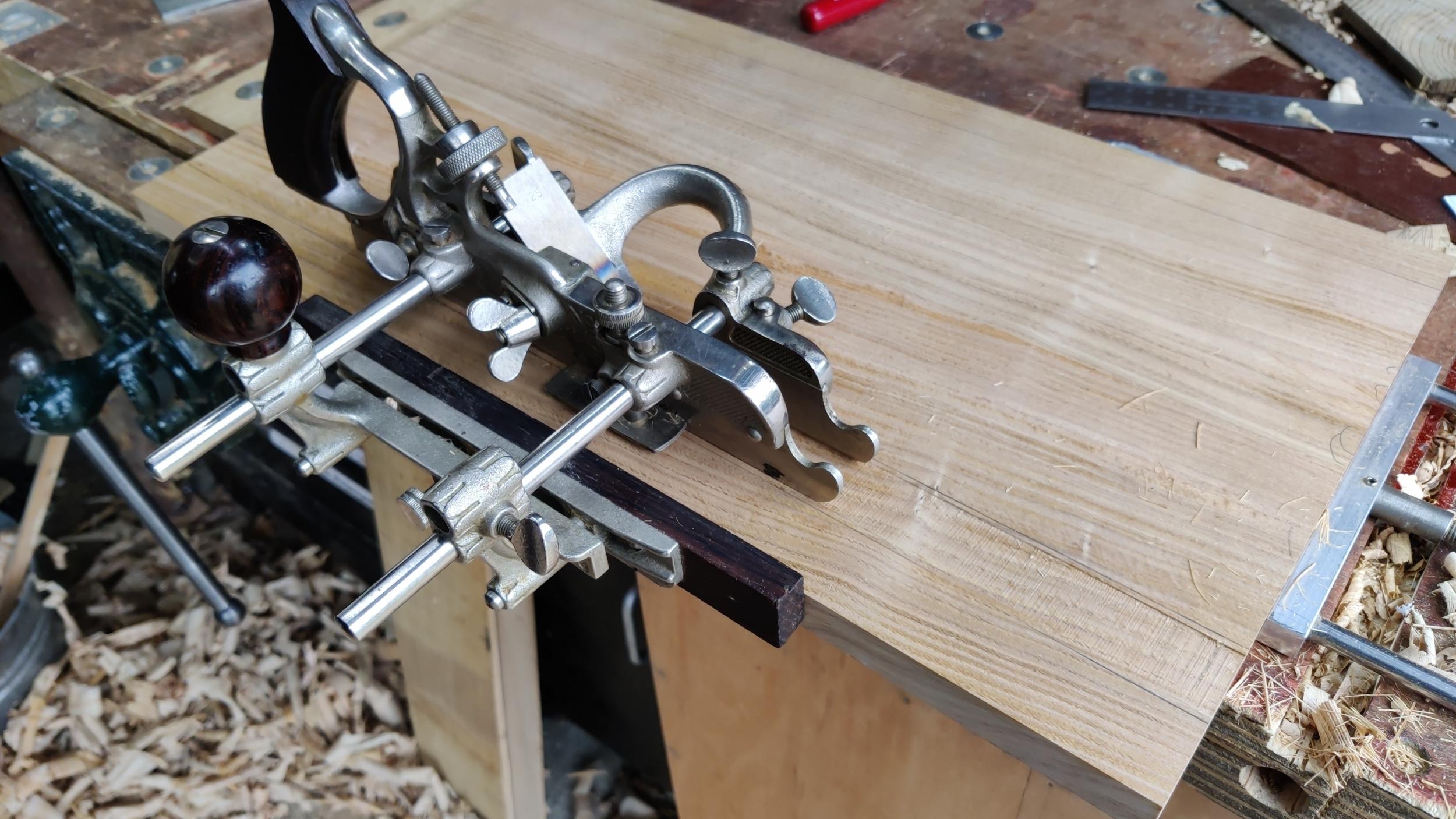
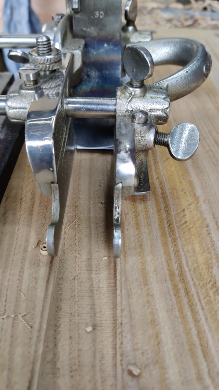
As it's quite a wide groove to plough, I wanted to use both depth stops on the plough plane, but my #45 didn't come with the second depth stop. Thankfully, my #55 did and they seem to be the same part, so I could nick it off the #55.
I've never ploughed a groove wider than about 12 mm and was a bit nervous about going straight to 30 mm, so I decided to start with a (home-made) 25 mm blade. Due to the grain direction of the wood, I had to configure the plough plane for left-handed use (I'm going to be ploughing a groove on the other side of the board later, so turning the board round and using the other edge just would have put off the problem for the next groove).
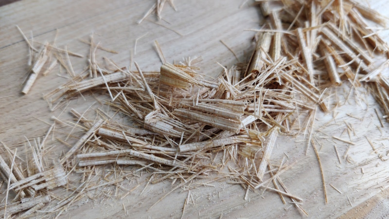
There was a lot of what I would (as a machinist) call chatter: the blade seemed to bounce along the surface quite a bit making some very strange looking shavings...
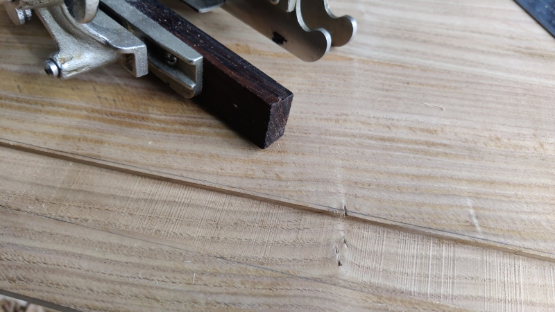
... and a pretty awful finish on the bottom of the groove:
I'd set the depth stops for a 4 mm deep groove with the intention of getting it down to 5 mm (the distance from the side of the block plane to the blade) later, so that juddery finish doesn't really matter, but it would have been nice to get a good finish off the plough plane. I'm guessing it's due to the width of the cutter and the lack of support over a substantial amount of its width.
With the 25 mm groove ploughed, I replaced the cutter with a 30 mm one and ploughed the sides down. This cutter took lovely (narrow) shavings, so I guess that confirms the theory that the unsupported width was the cause of the chattering.
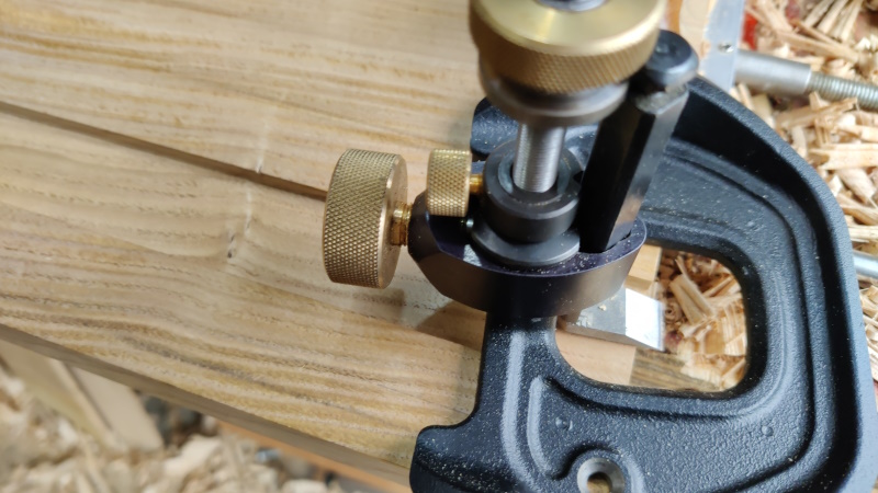
With the groove now the right width, I could take it down to depth with a router plane. This has the advantage of guaranteeing that the bottom of the groove is parallel to the surface of the shooting board. It also left a lovely finish, removing all that chatter from earlier.
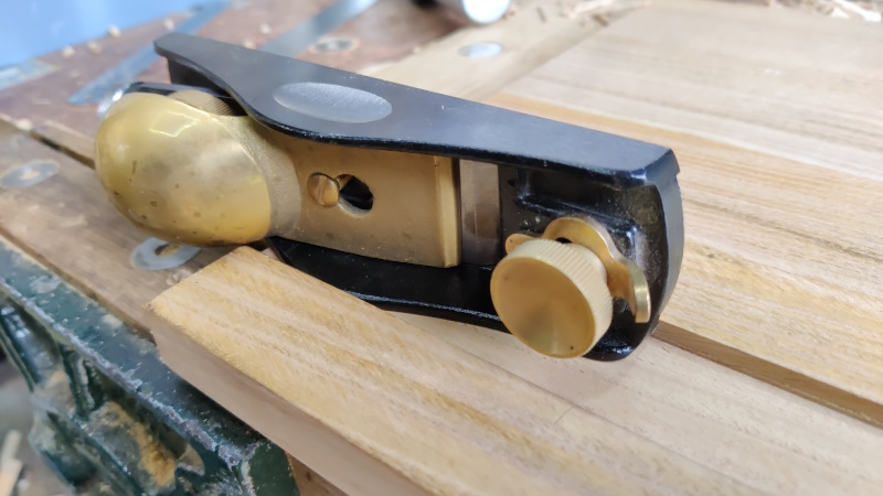
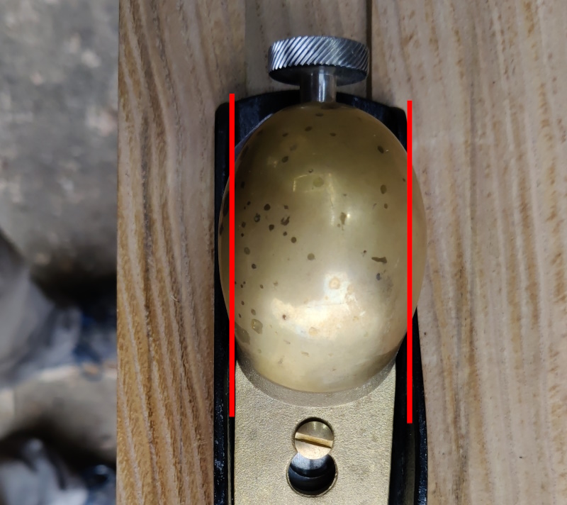
With the groove finished I could try putting the plough plane into it. The web fitted really nicely, but it was at this point I realised that the brass lever cap thing sticks out over the top of the web and hence interferes with the edge of the groove.
I decided that was a good point to stop and ponder on the options. The obvious possibility is to widen the groove to give space for the lever cap. However, if I do that then the only thing stopping the plane from moving sideways (resulting in an out-of-square cut) is the lever cap, which is a long way back from the cutting edge, so that wouldn't work very well.
I could widen the groove to the point that it becomes a rebate (i.e. take it all the way to the edge of the panel). That would get rid of any interference issues, but would mean there's nothing to stop the plane wandering to the right and again resulting in an out-of-square cut. The block plane is very light and hence doesn't have a lot of momentum, so it's quite easy for that to happen. I had the problem of planes wandering to the right on my older shooting board and the one in the photo near the start of this post was a complete revelation as it completely removed any chance of drift.
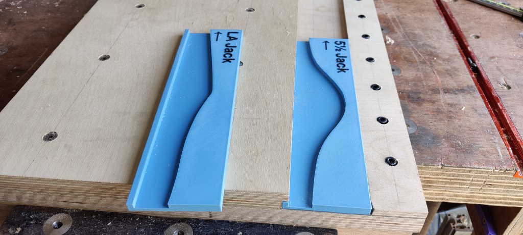
Another option would be to modify the groove to take a 3D printed carrier, a bit like the one used on my existing shooting board:
That would require a much deeper groove (to allow for the thickness of the base of the 3D printed carrier). It would also have to be wider. If I did it in exactly the same way as my existing shooting board, it would also require an undercut, but I could probably do without that if the carrier only supported the right-hand side of the plane and not the left.
Another really drastic option would be to reshape the block plane's lever cap, something like this:
I'm not sure whether I can bring myself to do that last one though...
Page 95 of 144
This website is free and ad-free, but costs me money to run. If you'd like to support this site, please consider making a small donation or sending me a message to let me know what you liked or found useful.

 Return to main project page