Travel Tool Chest & Workbench Build Process
Page 96 of 144
Posted 17th September 2023
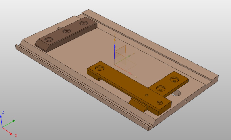
To give a bit of an idea of what I'm aiming for here, this is the current CAD model of the shooting board:
The idea is that the groove at the top-right of the image is used for conventional shooting, while the groove at the bottom-left of the image is used for mitre shooting. The perpendicular pieces are the fences for the workpiece to rest against (held in place with screws so that they can be adjusted for squareness), while the strange looking piece with the long housing cut into it will support the left-hand edge of the plane while shooting the mitres.
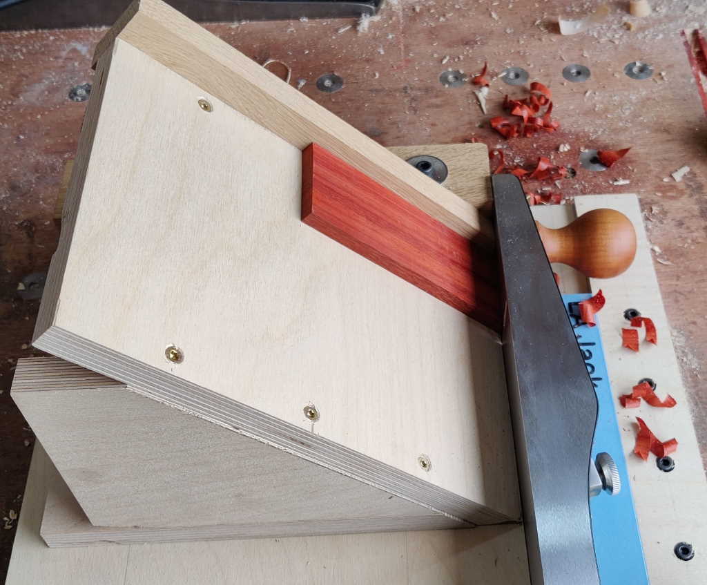
This is a completely different approach to mitre shooting compared to my existing shooting board, which looks like this:
I don't think the new shooting board is a particularly unusual design of mitre shooting: I'm sure I've seen similar things posted on the woodworking forum before as well as in other places. The main advantage is that it doesn't need a separate assembly (which would have to be dismantle-able to fit in the chest).
The only issue is that the 45° groove needs to be quite deep: if it is only a shallow groove supporting the edge of the plane then the top supporting piece would have to be quite high up and that would result in it not fitting into the front of the chest.
That groove was making me feel a bit nervous (hence arranging the wood the grain so that this one would be in the more natural orientation for cutting and the more conventional groove ended up being made left-handed).
After pondering on a few different approaches to making the groove, this is what I settled on...
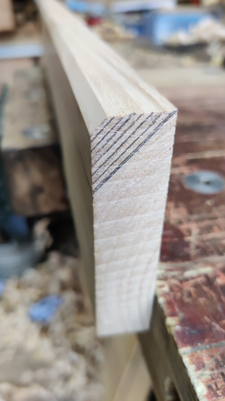
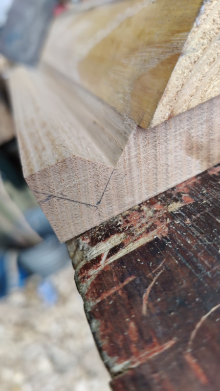
I started with an offcut of sweet chestnut (I've got rather a lot of those now) and planed one side flat and free of twist. I then used a small combination square to draw lots of 45° lines on the end grain at both ends:
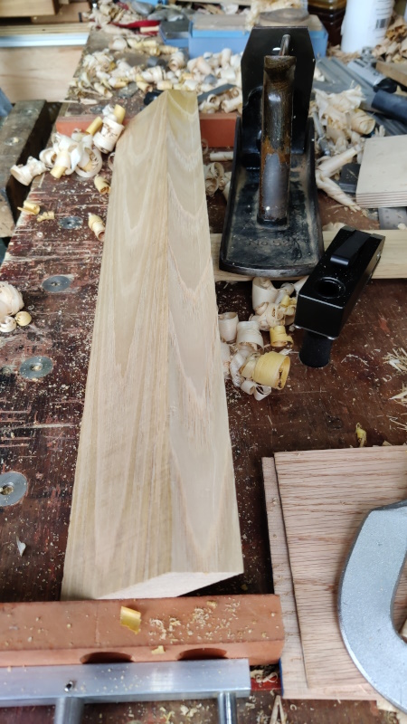
I then attacked it repeatedly with a #5½ until the mitre was complete, then kept tweaking and adjusting (finishing with a #7) until it was at the correct angle and also straight all the way along the board:
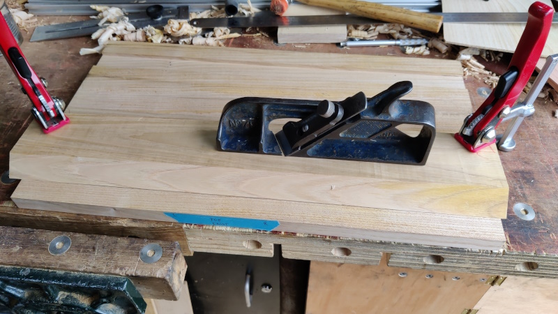
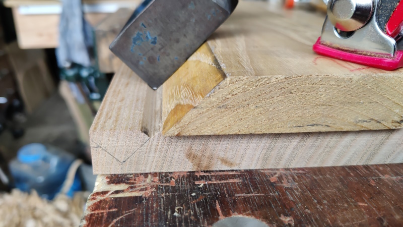
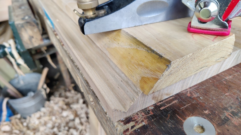
This reference piece could then be clamped to the shooting board and I used my recently acquired (from Bristol Design) Record 712 skew shoulder plane to cut the groove.
It was quite satisfying to watch the groove progress reasonably accurately along the reference line I'd drawn:
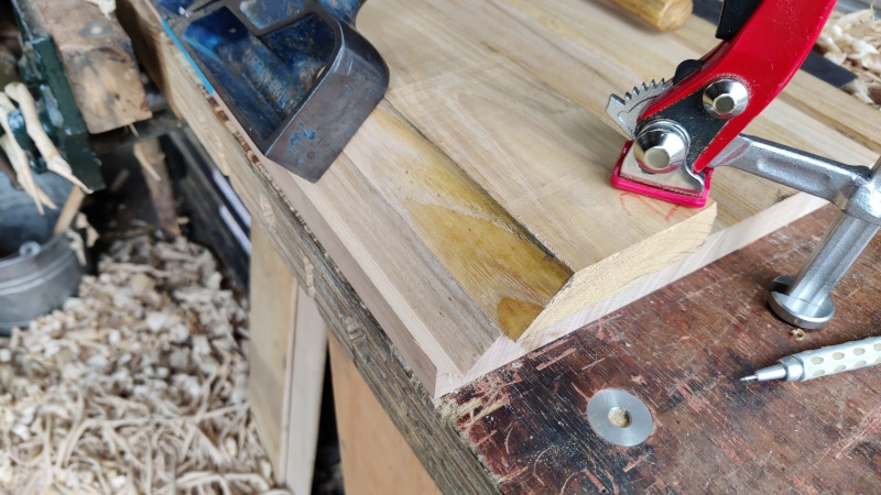
I kept going until the long side of the groove was 20 mm long (ish). There's enough of a reference surface there now that I should be able to tweak if necessary later.
That left a sharp corner, which was dealt with using the block plane:
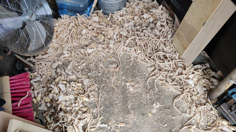
I think it might be time for a tidy-up soon...
Page 96 of 144
This website is free and ad-free, but costs me money to run. If you'd like to support this site, please consider making a small donation or sending me a message to let me know what you liked or found useful.

 Return to main project page