Cordless Power Tool Vacuum Cleaner Starter - Details
Page 2 of 10
3D Printed Parts
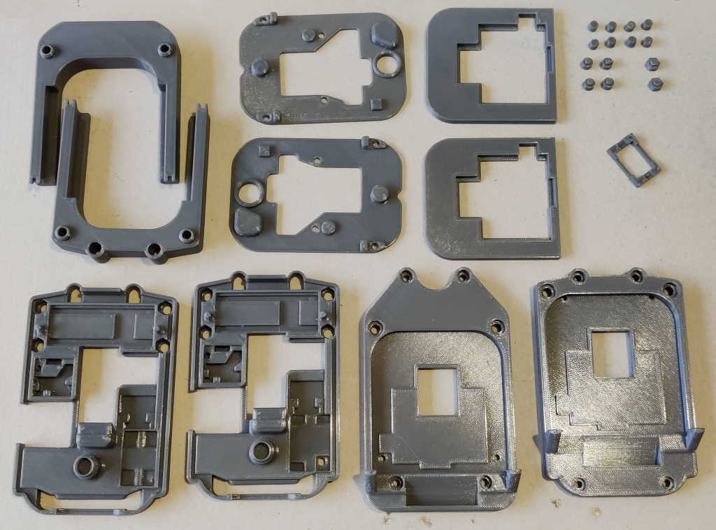
This picture shows all of the 3D-printed parts required to make both variants of the cordless tool vacuum starter. Most of the parts are identical for both variants, with only the battery holder top and base being different between the standard and offset variant. There are also some optional inserts for the offset variant that can be used to fill in a couple of holes. The parts are described in more detail below. All parts are available for download from here, including STEP files which can be used if you want to tweak the design in any way. With some careful arrangement, all the parts for one vacuum starter will fit on the bed of a Prusa i3 MK3S+ 3D printer.
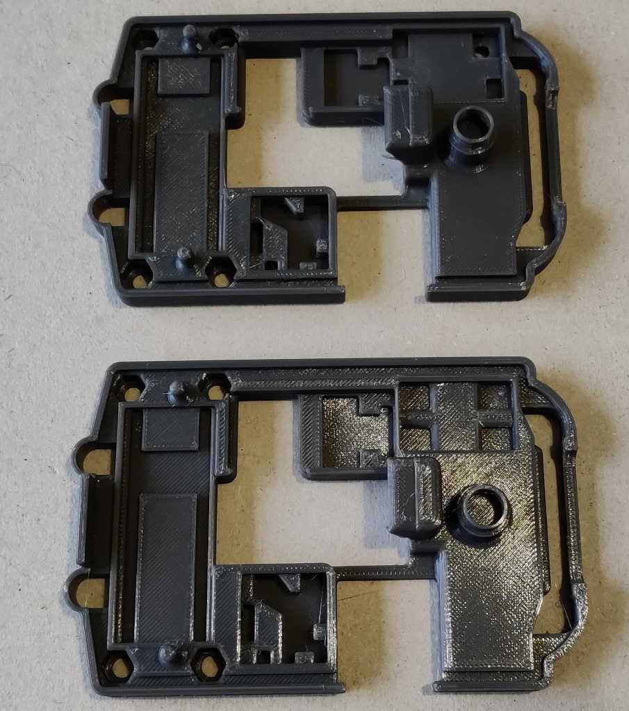
These parts are the PCB holders. They are identical for both variants. They are one of the more complicated shapes in the design and the shapes serve a number of purposes:
- Providing pockets in which the electronic components sit;
- Providing a locating feature for the spring that pushes the battery clip upwards;
- Providing a support for the top (contact) PCB.
Although the parts are identical for both the standard and offset variants, there are four versions of the design available. I've designed the unit to work with a three different power supply boards. There are two designs of PCB holder that can used with the largest power supply board; the other two work with either the medium sized one (which I recommend) or the smallest one. More details of the power supplies are included on the page about purchased parts. There are also variants for two different battery case kits (denoted "Case Variant A" and "Case Variant B"). You can read a bit more about the differences on the purchased parts page.
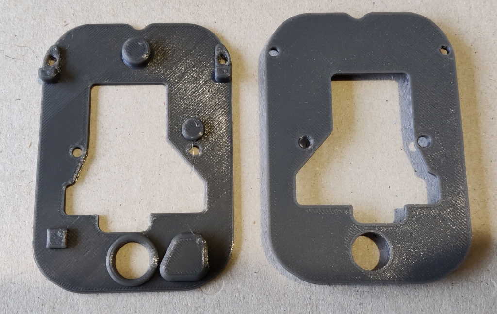
These parts are the PCB retainers. They are identical for both standard and offset variant but there are two versions for different battery case kits; the retainer is held in by friction alone (although once assembled it is also clamped by the outer case). The various "lumps" on the panel press down on the components in the PCB holder and ensure they don't lift out of their pockets.
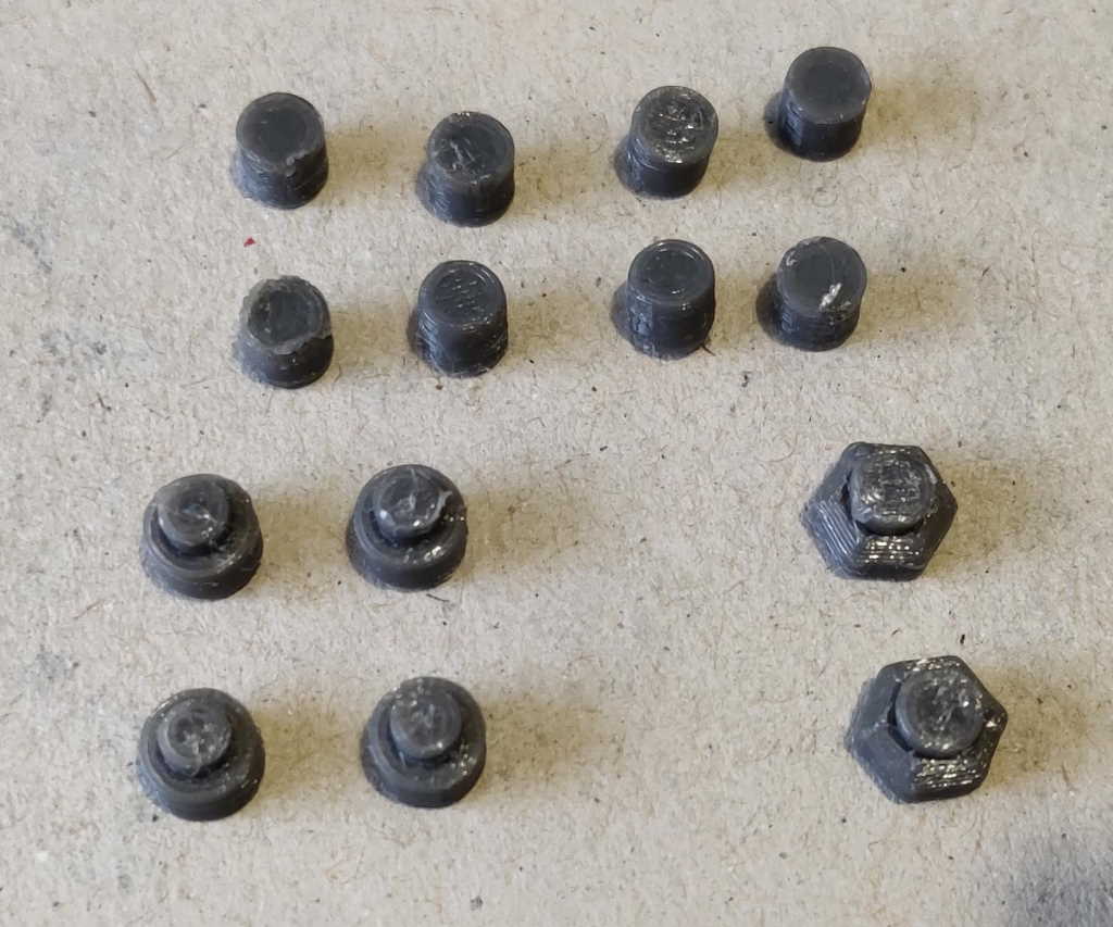
The small pieces in the first image are:
- Alignment pieces (four per unit, shown as the 8 parts at the top of the image): these are used to align the battery holder bases to the PCB holders.
- Top board support pieces (two per unit: bottom left): these clip into the PCB retainers and support the board that connects to the power tool.
- Infill pieces (bottom right): these are (optionally) used with the offset variant to fill in a couple of exposed holes in the PCB holder.
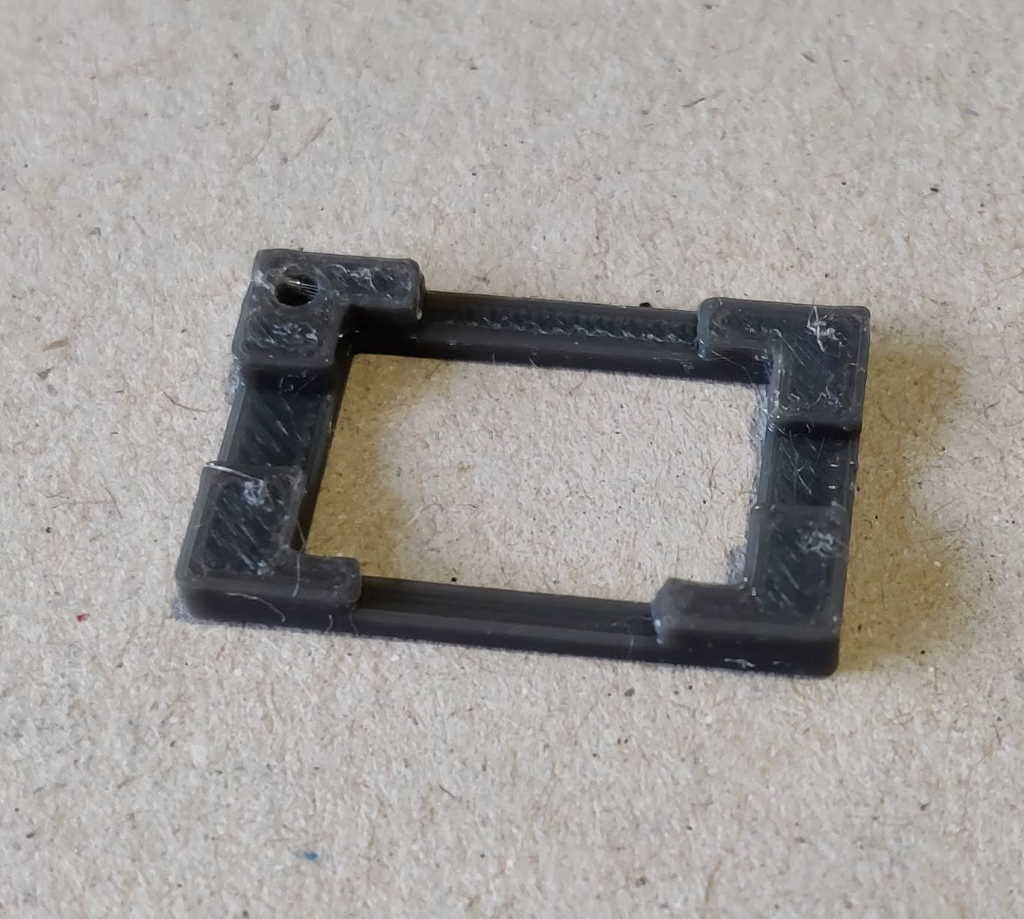
The right-hand image shows a border piece that is used with the smallest of the supported power supply boards.
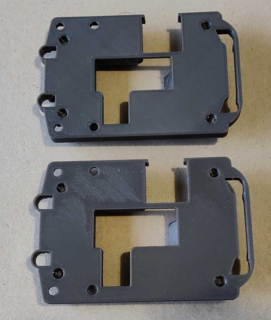
These parts are the battery contact retainers and are used to retain the connector that attaches to the battery. They are identical for both variants.
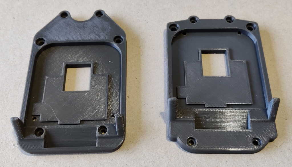
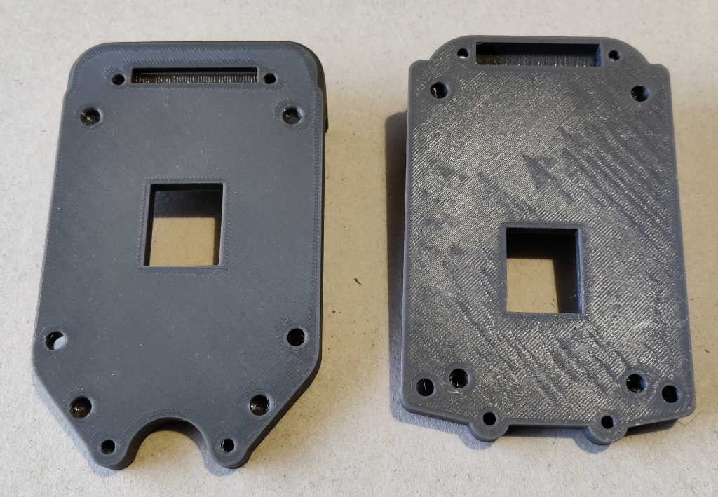
These parts are the battery holder bases for the offset variant (left of each photo) and the standard variant (right of each photo). The battery contact retainer fits into the slot in the battery holder base and between them they retain the connector that attaches to the battery.
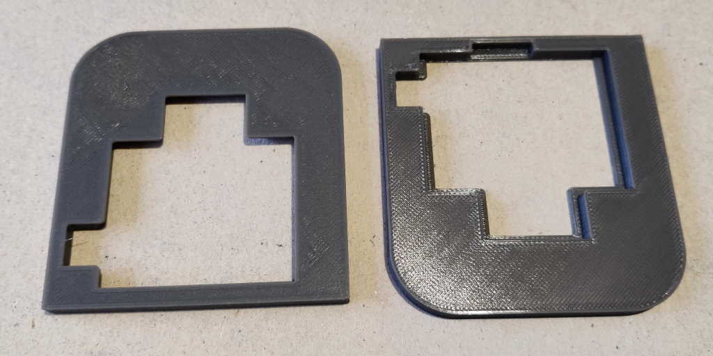
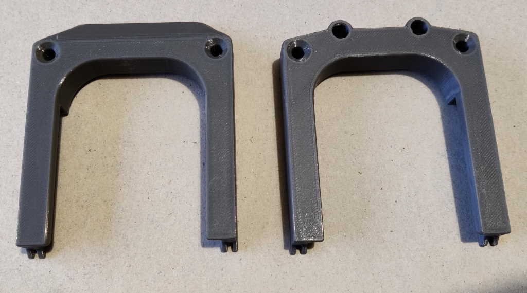
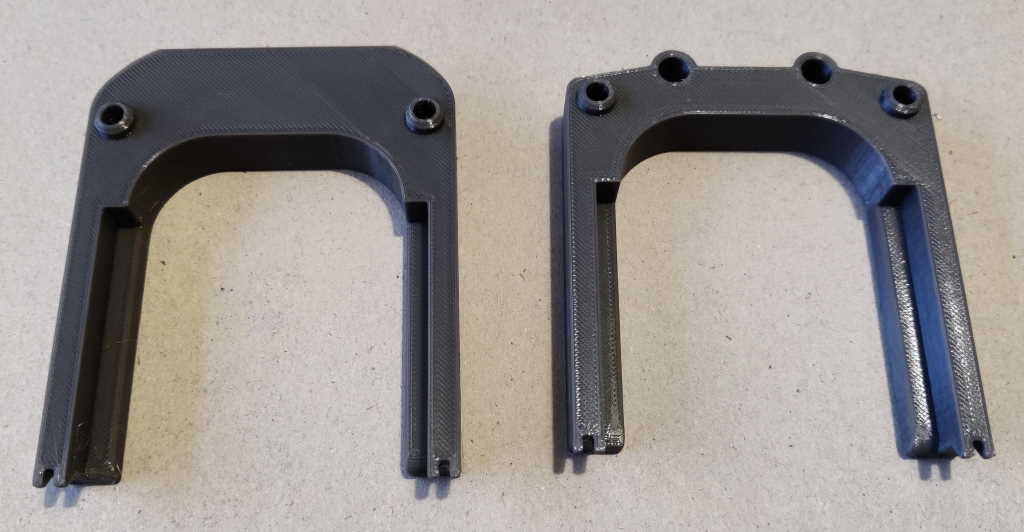
These parts are the battery holder tops for the offset variant (left of each photo) and the standard variant (right of each photo). They clip into the battery holder base and hold the Makita battery in place.
Page 2 of 10
This website is free and ad-free, but costs me money to run. If you'd like to support this site, please consider making a small donation or sending me a message to let me know what you liked or found useful.

 Return to main project page