Cordless Power Tool Vacuum Cleaner Starter - Details
Page 5 of 10
Assembly
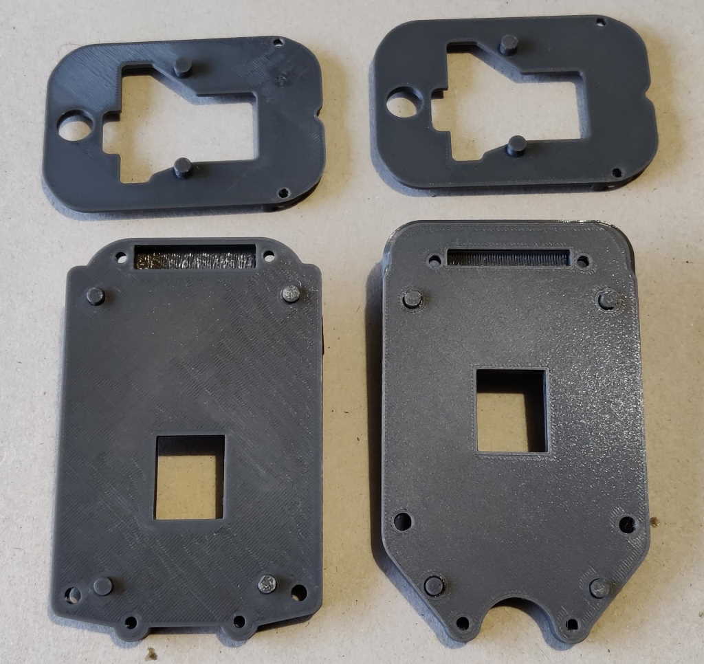
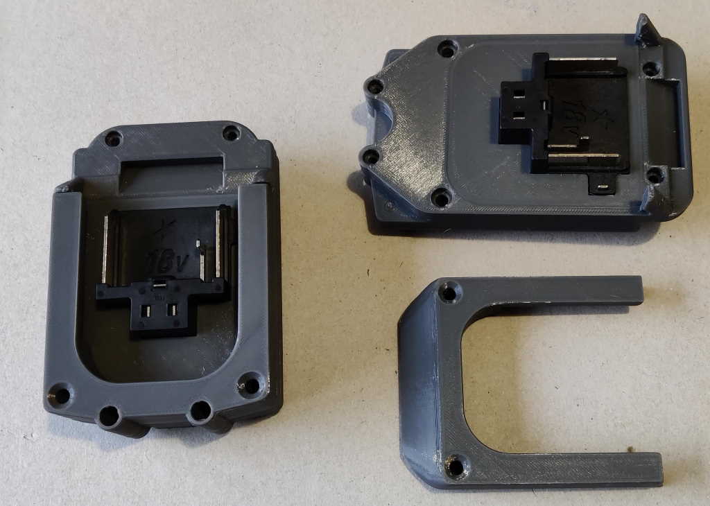
The first stage of the assembly process is to push the four alignment pieces into the PCB holder (bottom) and the two top board support pieces into the PCB retainer (top).
If you're making the offset variant and want to fill in the exposed holes, you can now also fit the infill pieces into the PCB holder to fill in the unused holes.
The battery holder base is then pushed onto the PCB holder; the alignment pieces help keep the two parts properly aligned and hold them together until the screws are tightened at the end of the assembly process.
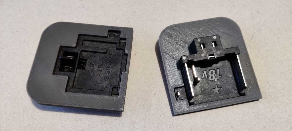
The battery contact is then fitted to the battery contact retainer.
This is then pushed firmly into the battery holder base (make sure it is pressed in all round) and then the battery holder top can be levered into place.
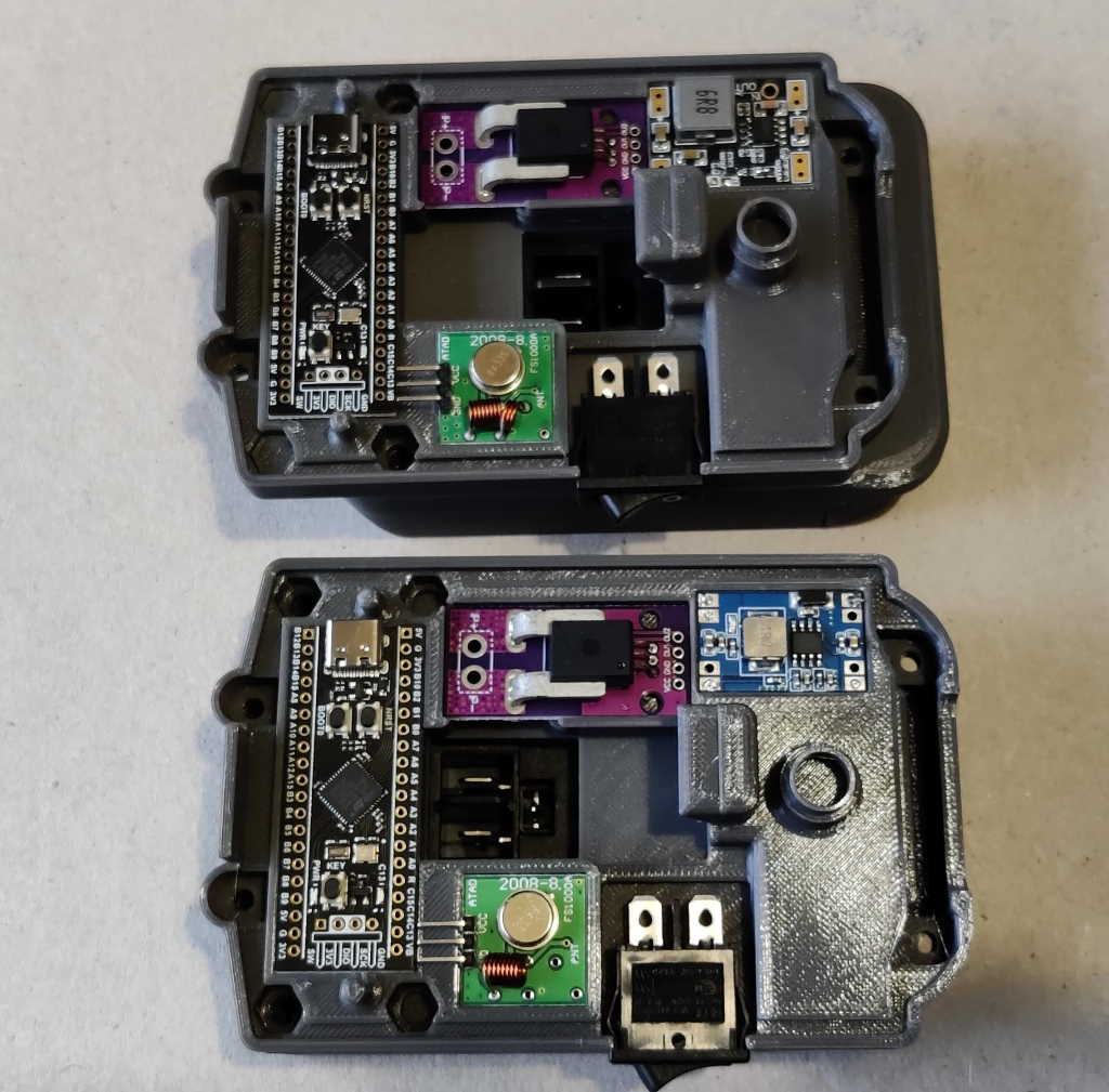
This photo shows how the PCBs are arranged in the PCB holder. Note the orientation of the STM32F411 development board with the USB-C connector nearest the current sensor and the orientation of the DC-DC converter PCB with the output connections nearest the current sensor. Now that you've confirmed that everything fits properly and doesn't need the PCB sizes adjusting with a hand file, take all the components back out again: you shouldn't do the soldering in situ as the heat is likely to melt the plastic components.
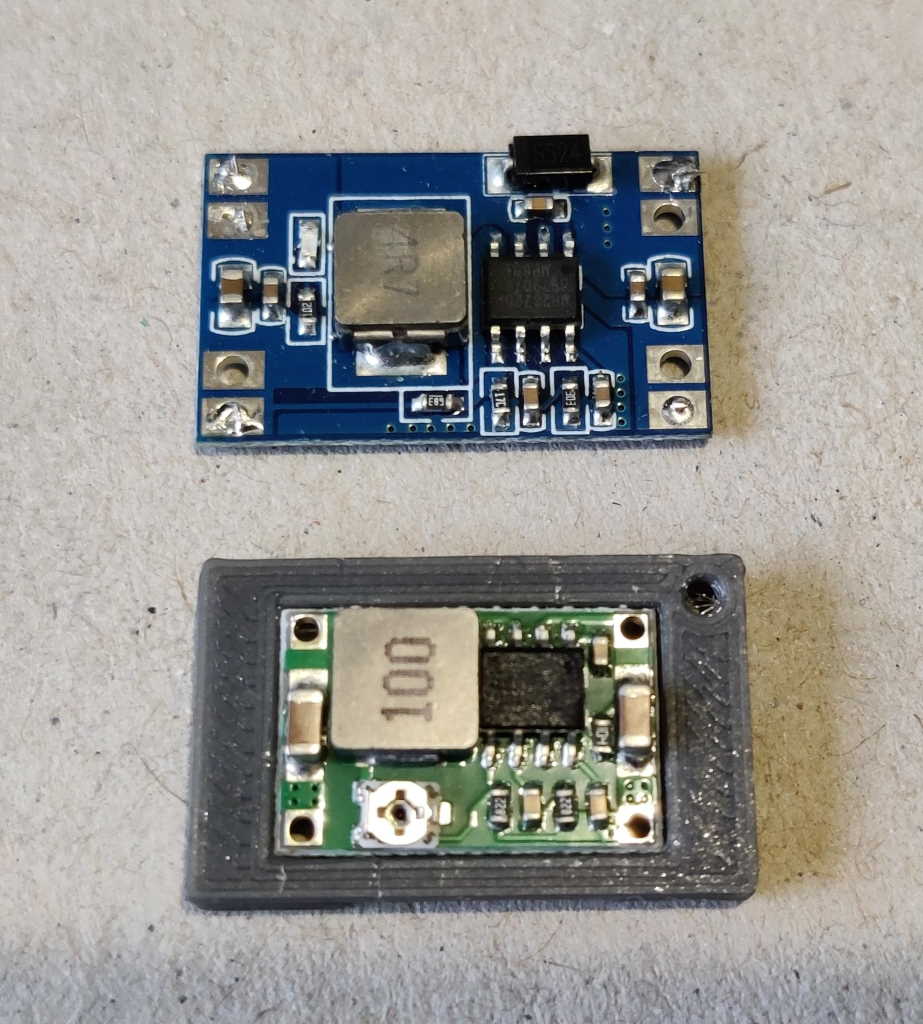
Note that if you're using the smallest power supply, the border piece is used to match the size of the medium-sized power supply.
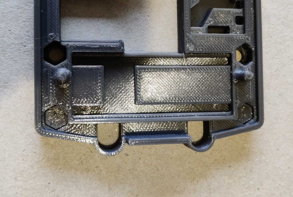
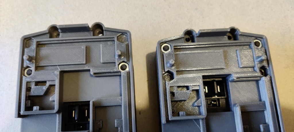
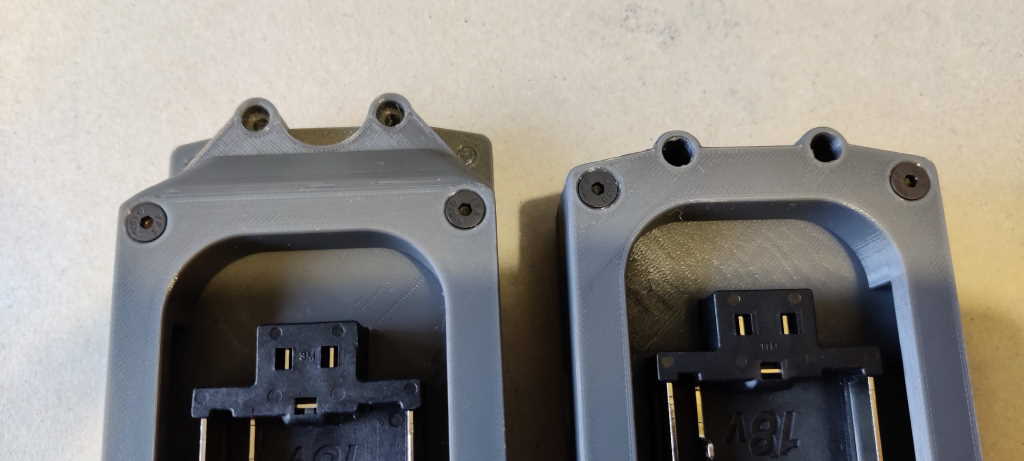
The M4 nuts should now be pressed firmly down into the hexagonal sockets. For the standard variant, two nuts are pressed into the PCB holder in the outer positions: see the right-hand side of the above photo. For the offset variant, two nuts are pressed into the PCB holder in the middle positions: see the left-hand side of the above photo.
You can now use the M4×30 mm countersunk screws to hold the battery holder to the PCB assembly. It is only held at one end; the other end will be held together firmly by the screws that came with the battery case kit.
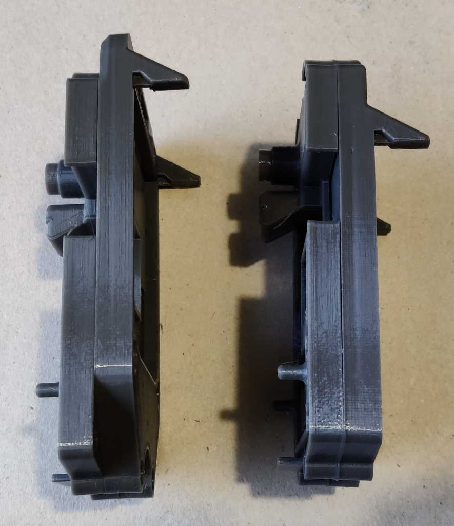
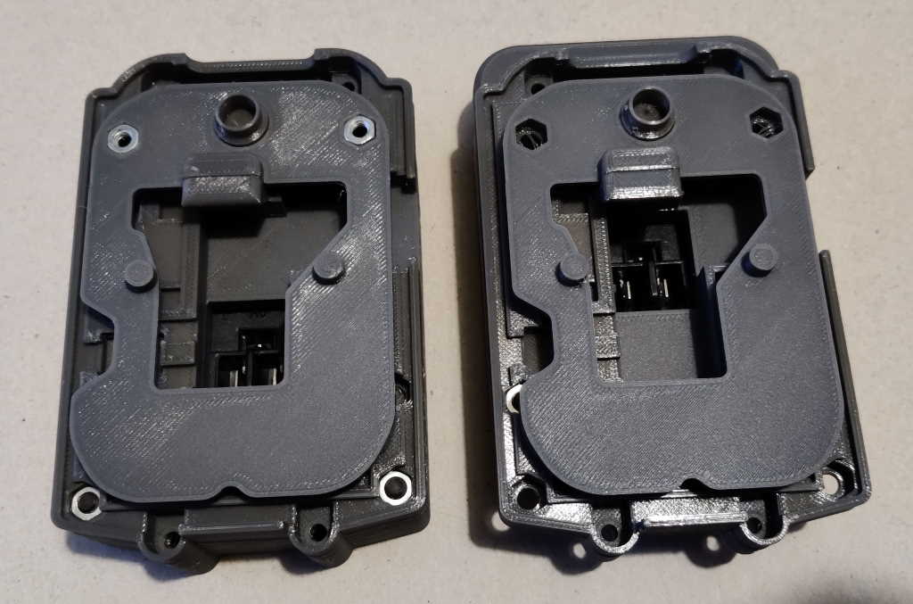
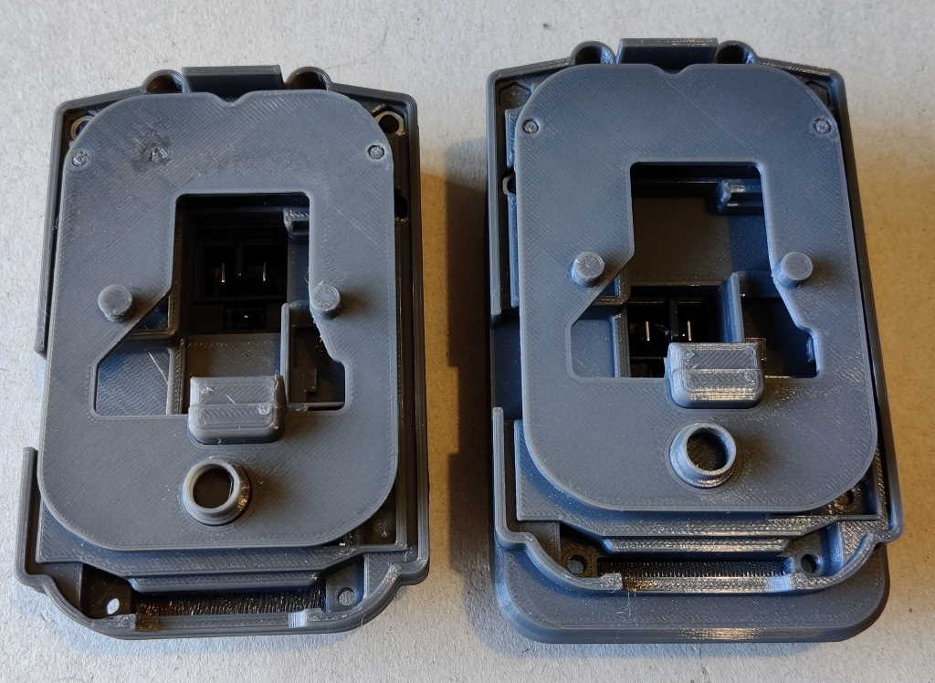
These photos show what the PCB retainer looks when fitted without any wiring connected. The PCB retainer is deliberately quite a tight fit, so you may want to complete the soldering before fitting it. If you do so, make sure you've looked carefully at how the PCB retainer fits so you can make sure the wiring doesn't interfere with it.
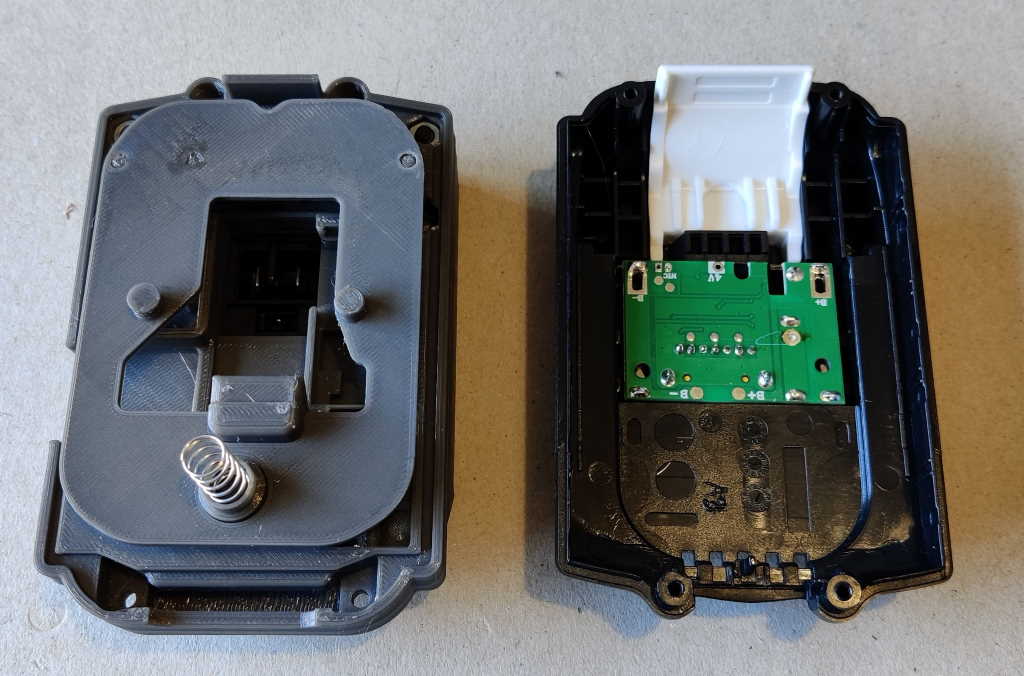
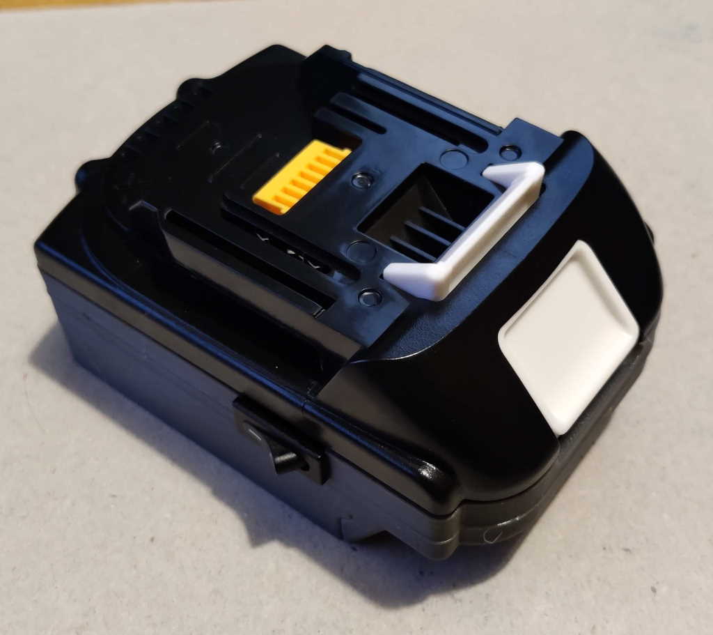
This photo shows where the spring sits in the PCB holder and where the top contact PCB goes in the top black plastic component from the battery case kit.
This photo shows what the final assembly (for the standard variant) looks like. Now that everything is assembled and shown to fit properly, we can move on to soldering the connections.
Page 5 of 10
This website is free and ad-free, but costs me money to run. If you'd like to support this site, please consider making a small donation or sending me a message to let me know what you liked or found useful.

 Return to main project page