Cordless Power Tool Vacuum Cleaner Starter - Details
Page 6 of 10
Soldering / Modifications
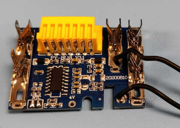
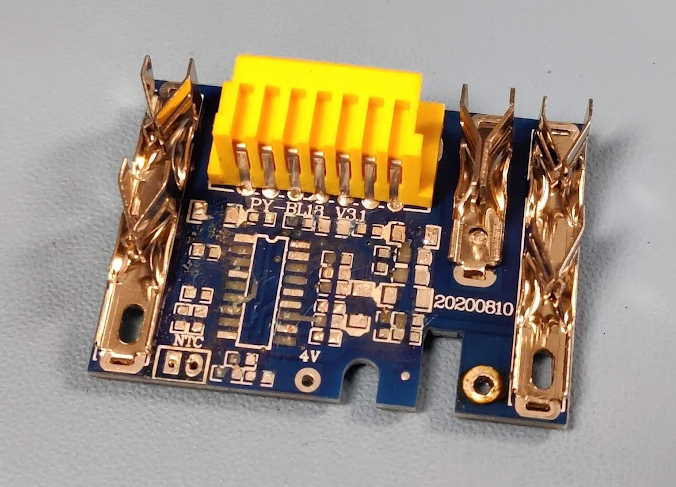
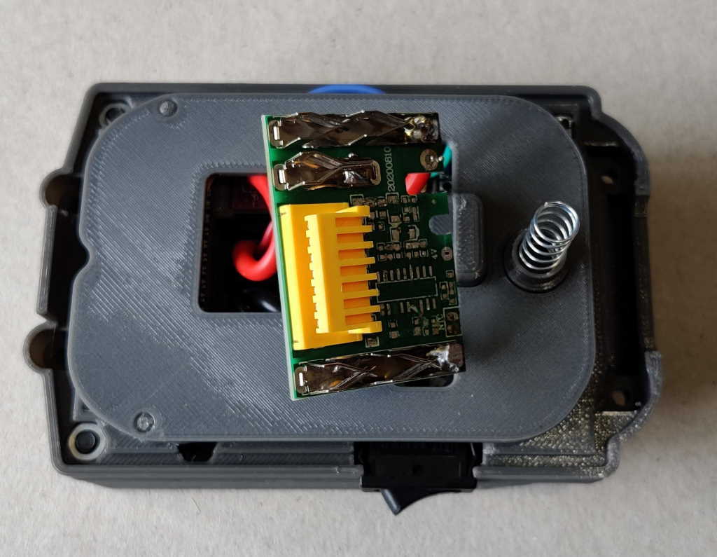
The first step is entirely optional and possibly unnecessary. I chose to desolder (remove) most of the components from the top contact board. The only reason why this is needed is that it means that you can (I think) safely plug the battery & vacuum starter into your charger. All being well, it won't actually charge (it'll produce an error light). The risk if you don't make this modification is that there's a chance it might try to charge and damage your battery in the process. I don't know enough about how the circuit works to know exactly what would happen.
If you do decide to desolder the components from the board, remove everything except the orange connector and the three battery contacts. If you decide not to desolder components, just cut the black wires attaching the thermistor as close as possible to the PCB.
The thermistor MUST be removed (but you may want to keep the wire to use for the thermistor connection if you don't have any similar gauge wire).
The next step is to wire everything up.
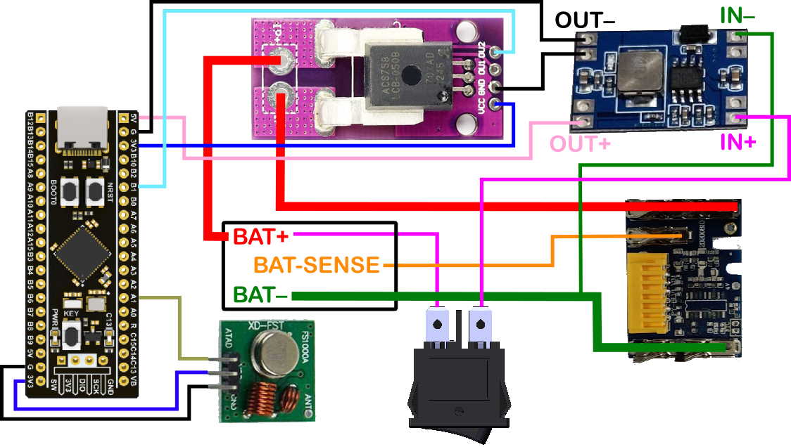
This diagram shows the wiring required for the remaining components of the board (click on it to see a bigger view). Obviously, all the connections have to be correct for it to work, but in particular, BE VERY CAREFUL to ensure:
- You connect all three battery contacts on the battery connector to the matching battery contacts on the top board (one via the current sensor).
- You use suitable thickness wire for the power connections (drawn as thicker lines in the wiring diagram). I used 2 mm² (14 AWG) wire for the power tool connections and 0.2 mm² (24 AWG) wire for the other connections. I haven't checked the currents in each wire, so choose your wire at your own risk.
- You connect the positive battery connector to the positive input terminal on the DC-DC converter board and the negative battery connector to the 0 V input terminal on the DC-DC converter board.
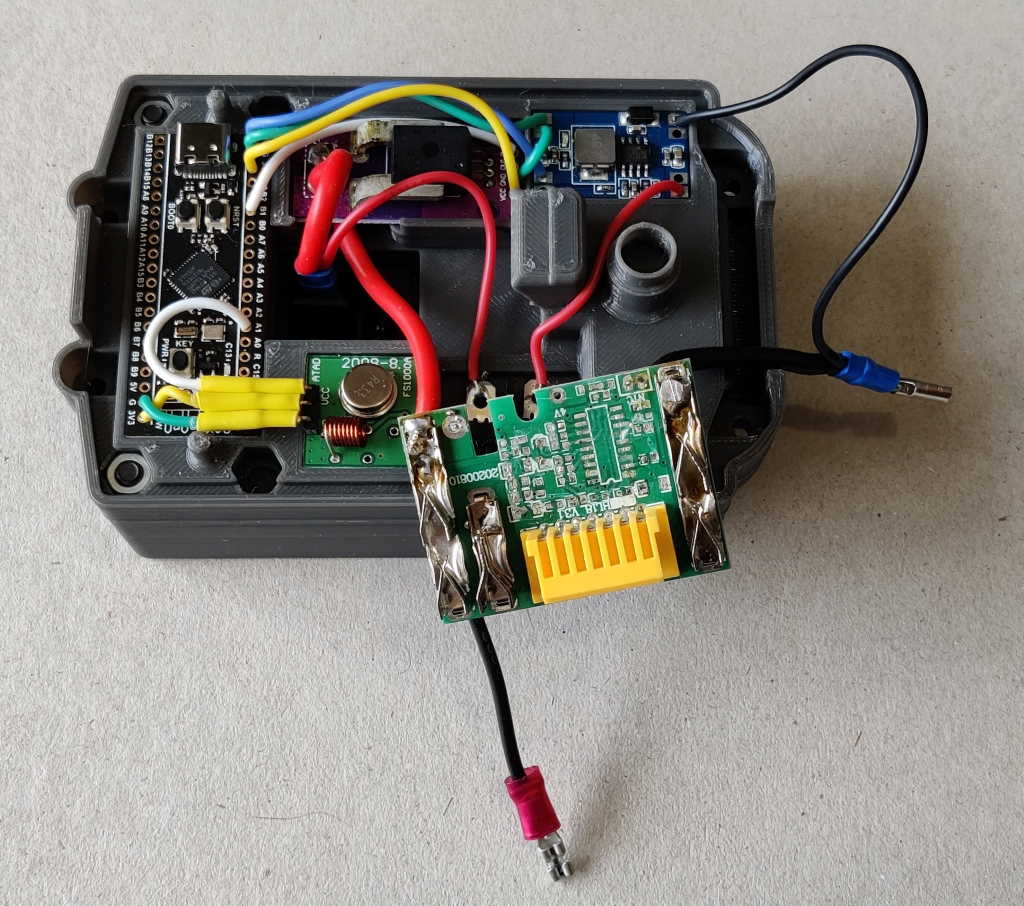
This photo shows what it looks like when everything is connected up. Before fitting the PCB retainer and completing the assembly process, it's worth doing some basic checks:
- Double-check the wiring against the wiring diagram: if you get something wrong it could damage something when you turn it on, so it's better to check again and be sure.
- Connect the battery to the bottom of the unit, turn on the rocker switch and make sure the power LED on the microcontroller comes on. If it doesn't, something's wrong with the wiring (and there's a risk you might have done some damage).
- If you have a multimeter or an oscilloscope, put the 0 V (also inaccurately known as "ground") connection on the negative output pin from the DC-DC converter and check the voltage on the four small connections on the current sensor PCB. The pin labelled VCC should be at 3.3 V, the one labelled GND should be at 0 V and the other two (OU1 & OU2) should be at approximately 1.65 V.
- With the remote controlled socket plugged into the mains, press the push button marked "KEY" briefly. The LED marked "C13" should come on and the remote controlled socket should turn on. Press the push button again and the remote controlled socket should turn off. Press it one more time and the LED marked "C13" should turn off.
If that all works, you can now take the Makita battery off and fully assemble the unit. Then give it a try! If that (or any of the previous tests) fails, go to the next page for some tips on diagnosing issues.
If it works and you find it useful, please post some photos of your build on the STL download site. Also if you appreciate the amount of time and effort that I've put into designing this tool, consider making a donation to help pay for the running costs of this website.
Page 6 of 10
This website is free and ad-free, but costs me money to run. If you'd like to support this site, please consider making a small donation or sending me a message to let me know what you liked or found useful.

 Return to main project page