Cordless Power Tool Vacuum Cleaner Starter - Details
Page 8 of 10
Using Other Radio Controlled Power Sockets
The source code for the microcontroller program that transmits the codes is designed to be easily tweaked for different power sockets. I've tested it with Dewenwils sockets and done some rudimentary assessment on some Energenie and Etekcity devices, but it should be very straightforward to add support for other sockets. However, some fairly detailed information is required.
All of the units I've tested follow the same pattern:
- 25 bits of data transmitted in each packet (although this is easily adjustable if different units use different packet lengths).
- Each bit is the same length (but the bit length is different for different manufacturers) and consists of a high pulse and a low pulse. For the bits I call "0", the high pulse is 25% of the time and the low pulse is 75% of the time. For the bits I call "1", the high pulse is 75% of the time and the low pulse is 25% of the time.
- There is a fixed pattern of 1s and 0s that is manufacturer specific (although the five pack of Dewenwils remote sockets I bought use a different code to the single Dewenwils socket I bought) and towards the end of this pattern, there is an area for the specific socket to be identified (i.e. to distinguish between multiple sockets if you have more than one) and one or more bits to indicate whether to turn on or turn off.
That's really it to be honest. The information required to set up a new device is then:
- The bit period (time between rising edges of the waveform).
- The code you get when you press each button on the remote control (as a string of 1s and 0s).
- The manufacturer of the device.
I found that I hadn't quite got the timing right when I used this method, so it's likely that you'll need one or more extra goes to tweak the bit period until it perfectly matches the signal coming from the remote control.
For more information, this is (at the time of writing), the configuration table (config.py) that holds the information on the various socket types:
config = [
        {
            "Manufacturer": "Dewenwils",
            "Name": "FivePack",
            "BasePattern": 0x08A20A0,
            "OffPattern": 0x00,
            "OnPattern": 0x10,
            "UnitCodes": {
                "1": 0x8, "2": 0x4, "3": 0x2, "4": 0xA, "5": 0x6
                },
            "NumberOfBitsInPattern": 25,
            "BitPeriodMicroseconds": 1076,
            },
        {
            "Manufacturer": "Dewenwils",
            "Name": "SingleUnit",
            "BasePattern": 0x0240048,
            "OffPattern": 0x00,
            "OnPattern": 0x10,
            "UnitCodes": {
                "0": 0x0,
                },
            "NumberOfBitsInPattern": 25,
            "BitPeriodMicroseconds": 1076,
            },
        {
            # The details here aren't quite right: it seems to switch sometimes,
            # but not consistently.  None of my remote controls work any more,
            # so I can't compare with the real thing to verify operation.
            "Manufacturer": "Energenie",
            "Name": "FourPack",
            "BasePattern": 0x1BD2D20,
            "OffPattern": 0x00,
            "OnPattern": 0x02,
            "UnitCodes": {
                "1": 0x1C, "2": 0x0C, "3": 0x14, "4": 0x04
                },
            "NumberOfBitsInPattern": 25,
            "BitPeriodMicroseconds": 2188,
            # Including the following overrides the default 25%/75% on time.
            # I don't know whether this is needed, but it's included as an
            # example.
            "OnTimeOverrides": {
                "0": 570,
                "1": 1640,
                },
            },
        {
            # Everything in the Etekcity spec is likely to be wrong!
            # My remote controls have stopped working, so I can't get
            # the code or the frequency out properly.
            "Manufacturer": "Etekcity",
            "Name": "ThreePack",
            "BasePattern": 0x028C006,
            "OffPattern": 0x00,
            "OnPattern": 0x00,
            "UnitCodes": {
                "1": 0x0C60, "2": 0x0D80, "3": 0x1E00
                },
            "NumberOfBitsInPattern": 25,
            "BitPeriodMicroseconds": 1708,
            },
        ]
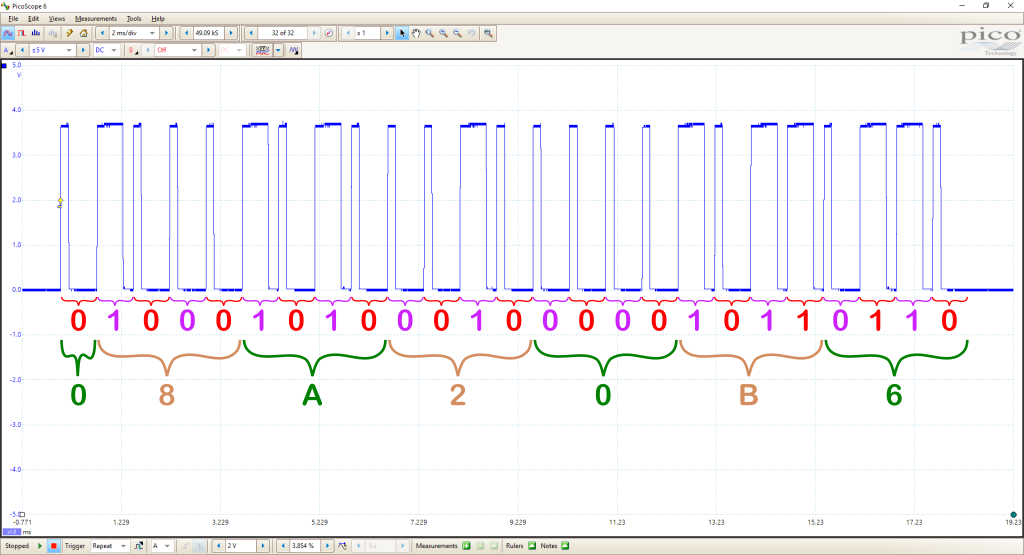
An example of what you might see on an oscilloscope for a transmitted packet is shown below with some notes on what you can see. The packet being transmitted is the one to turn Dewenwils unit 5 on. In this case, the packet is the bitwise-or of 0x08A20A0 (base pattern), 0x10 (turn on) and 0x6 (unit 5), giving 0x08A20B6 or 0b 0 1000 1010 0010 0000 1011 0110.
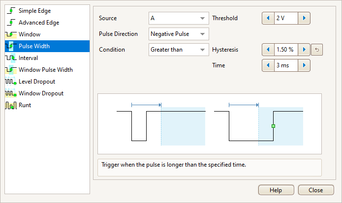
In case it's helpful, these are the trigger settings that I used in the Picoscope software:
Other oscilloscopes should support the same type of triggering, although it may be called something else.
If you just want to get one socket working (i.e. you don't care about supporting all of the various sockets in the list) you really only need to know three details: the period (which might take a bit of tweaking), the code when you send an "off" command and which bits change when you send an "on" command. Assuming that the change from "off" to "on" only involves one or more bits changing from 0 to 1 (and none changing from 1 to 0), you can then add another entry to the list in config.py:
{
    "Manufacturer": "MyCustomSocket", # Whatever you want to call it
    "Name": "SocketName",             # Ditto
    "BasePattern": 0x0ABCDEF0,        # Put the pattern that you read when pressing the "off" button here
    "OffPattern": 0,                  # Leave as zero
    "OnPattern" 0x040,                # This is a representation of the bit (or bits) that change when you press "on"
    "UnitCodes": {                    # If you're only adding a single socket, this can be just "0": 0
        "0": 0,
        },
    "NumberOfBitsInPattern": 25,      # This is 25 for every socket I've tested
    "BitPeriodMicroseconds": 1000,    # This will need tweaking - see below
    },
Setting the bit period correctly will probably take a few goes as the way the timer is implemented isn't perfect. Pick a number that's about right and then compile the code. Load it onto the microcontroller and use the "KEY" button to switch the microcontroller into the mode where it transmits continuously. Use the oscilloscope to work out the time from the start of the first bit in the pattern to the start of the last bit in the pattern. Press the "KEY" button until it stops transmitting and then take the same measurement using the remote control for your socket. You should then be able to scale your original value to get the correct bit period.
For example, let's assume that the "BitPeriodMicroseconds" you set when you compiled the code was 1000. Multiply 1000 by the time (in milliseconds) you wrote down for the remote control transmission and then divide the result by the time (in milliseconds) you wrote down for the transmission from the microcontroller. Round the result to the nearest integer and put that number into "BitPeriodMicroseconds". Recompile and repeat the test to make sure that the microcontroller's bit period is as close as possible to the remote control's bit period.
Page 8 of 10
This website is free and ad-free, but costs me money to run. If you'd like to support this site, please consider making a small donation or sending me a message to let me know what you liked or found useful.

 Return to main project page
