Cordless Power Tool Vacuum Cleaner Starter - Details
Page 7 of 10
Diagnosing Issues
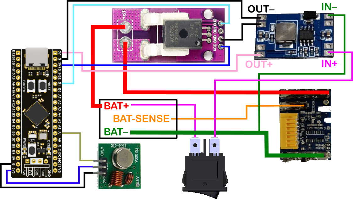
If the unit doesn't work as intended, the first thing to do is to double check that all the wiring is connected up correctly. Beyond that, you're going to need an oscilloscope and/or a serial lead such as this one. Here are some things you can check:
- The voltage on the signal pin of the current sensor (with respect to the black OUT-/G net shown on the wiring diagram) should be approximately 1.65 V when no current is flowing.
- Each time you press the button marked "KEY" on the development board, the unit will cycle through three different operating modes, which can be used to test the signals being sent to the remote-controlled socket:
- Normal mode - monitor current and transmit "turn on" and "turn off" as appropriate. C13 LED will be on if transmitting.
- Forced transmission of "Turn On"; C13 LED will be on.
- Forced transmission of "Turn Off"; C13 LED will be on.
- If you hold down the button marked "KEY" for more than 2 seconds, the unit will switch into a special mode in which, rather than transmitting "turn on" or "turn off" commands, it will transmit the measured current (note that this is transmitted in big-endian format using the 0 and 1 format described in the page about using other sockets; the units are not amps - they're ADC bits). You'll need an oscilloscope and a 433 MHz receiver board to make any sense of this! To get back out of this mode, disconnect the battery or switch the rocker switch to off.
- The 3.3 V serial lead can be used to see some rudimentary diagnostic information from the microcontroller. You'll need a serial terminal application such as putty and you'll need to work out which COM port has been allocated to your serial lead (on Windows this information is available in the Device Manager under ports). The serial port needs to be configured for 115200 baud. The microcontroller's transmit pin is A2 and this should be connected to the serial cable's receive pin. The microcontroller's receive pin is A3 and this can be connected to the serial cable's transmit pin. The 0 V pin of the serial lead should be connected to one of the pins marked "G" or "GND". Samtec PHT connectors are quite useful for making temporary connections like this.
- If you connect a 5 V power supply to the 433 MHz receiver board, you can use an oscilloscope to see what is being transmitted. A simple way of getting a 5 V power supply is to use the 5V and G (0 V) connections on the STM32F411 development board or the OUT- (0 V) and OUT+ (5 V) pins on the DC-DC converter board. Connect the oscilloscope up to either of the two data pins on the receiver board (with the return connection on 0 V) and set up the oscilloscope to trigger on negative pulse widths greater than 3 ms. See the next page for more information.
This last option, combined with the "KEY" mode switch is probably the most useful. Leave the unit in "Normal mode" (the C13 LED should be off) and press the "on" button on the remote control for your power socket. You should see the transmitted pattern on the oscilloscope display. Now stop pressing the button and briefly press the "KEY" push button on the "Black Pill" board so that it starts transmitting. All being well, the transmitted code should be the same (and the power socket will turn on). If the transmitted code looks different, either see the next page or save the waveforms somehow (CSV data files exported from the oscilloscope are best) and get in touch: I'll see if I can help.
Page 7 of 10
This website is free and ad-free, but costs me money to run. If you'd like to support this site, please consider making a small donation or sending me a message to let me know what you liked or found useful.