Woodturning Lathe Build Process
Page 4 of 43
Posted 9th February 2024
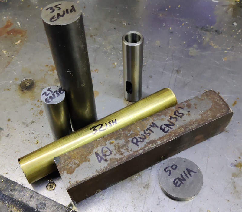
The first job of this afternoon was to assemble and roughly cut to length a subset of the materials I dragged out yesterday:
I've decided to make the spindle out of 35 mm EN1A. That has the advantage of being closer to the 30 mm inner bore of the bearings I've got (and hence I won't have to turn as much material away) and also the M33×3.5 thread I'm planning to put on the working end (for a possible future chuck purchase). The disadvantage is that a chuck won't really have much of a surface to bear against (because 35 mm isn't much bigger than 33 mm), but I've got a plan to help sort that out.
I started with the spindle. The length is a bit arbitrary, but hopefully should be long enough for chuck section, bearing, gap, bearing, two nuts to hold spindle in place, pulley, nut to hold pulley in place. This is all a bit haphazard, but I've got plenty of 35 mm EN1A (another reason for choosing it) so I can always have another go.
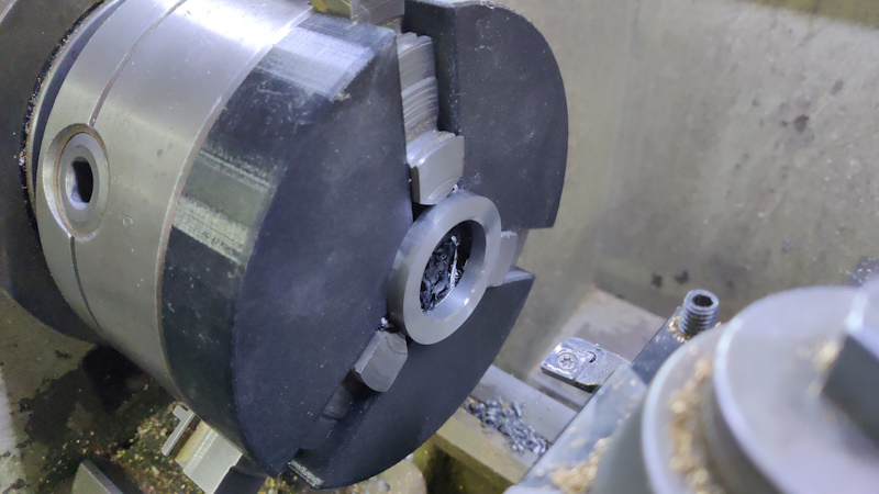
The first job was to take the slice of 50 mm EN1A, skim the faces (using a 3D printed chuck spider to help hold it a bit more easily) and drill then bore a hole that's about 34 mm diameter. I wasn't too worried about the actual size here as long as it was less than 35 mm and more than 33.5 mm.
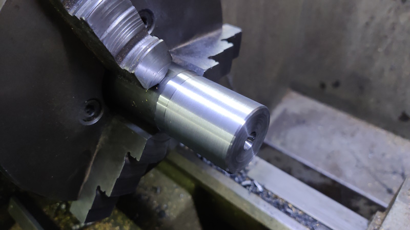
The first job for the actual spindle was to put the spindle in the chuck, face one end, reduce the outer diameter to 20 mm for a bit and stick a centre drill hole in the middle of it.
The reduced diameter will eventually form the surface that the pulley rests on, but for now I just wanted it somewhere near the right size.
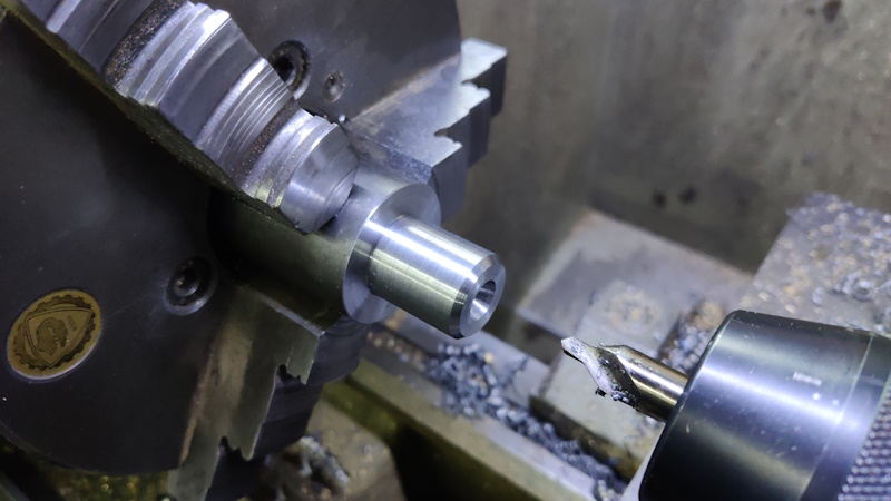
I then flipped it over and did a similar thing on the other end:
The first diameter reduction was to 33.5 mm for 37 mm length. That'll eventually become the M33×3.5 thread (for 33 mm) and then a plain 33 mm register after that for 4 mm. That's based on a document I found online for a typical chuck mount. Without a chuck, I can't really confirm whether that's right or not. The second (narrower but shiny) bit was made very carefully (lots of micrometer measurements) to be slightly larger than the bore I made in the 50 mm ring.
With that done, the spindle went in the freezer and the ring went in the kitchen oven on maximum temperature (about 250°C) and they were left for a bit while I got on with the next bit.
The next bit was working on the (80 mm long) 25 mm EN3B section, which was drilled through 8 mm and then drilled and reamed 12 mm to a depth of 60 mm. The reamed hole is overkill (it's a lots-of-clearance hole for an M10 thread so it really doesn't need to be reamed!), but reaming it was intended to help with one of the next jobs. The part also got a heavy chamfer on the end with the 12 mm hole.
I also mounted the Morse Taper adaptor thing (which has a 25.4 mm / 1" outer diameter) in a collet chuck and drilled, bored and reamed a 12 mm hole in the bottom of that. The boring operation was because the adapter was quite hard and the drills didn't seem too happy: I figured a carbide boring bar would cope better. This part also got a heavy chamfer.
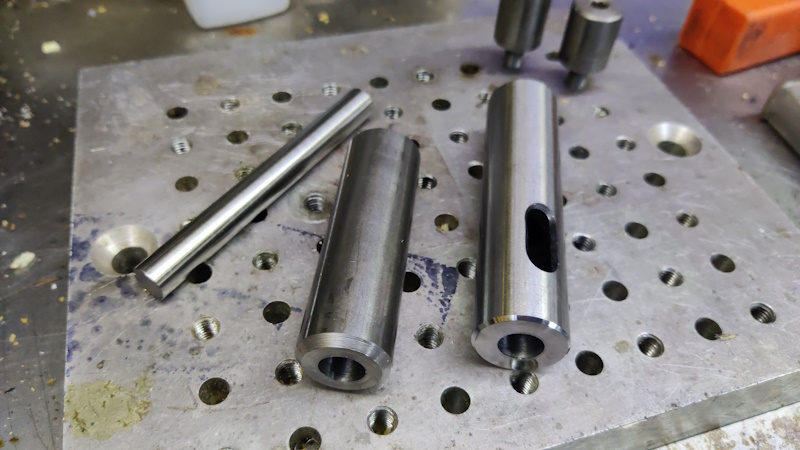
The other piece you can see in that picture is a bit of 12 mm silver steel, which is ground to a very accurate size. That went into the 12 mm hole and forced the two pieces to be aligned. Then it was TIG time (something I haven't done for a while):
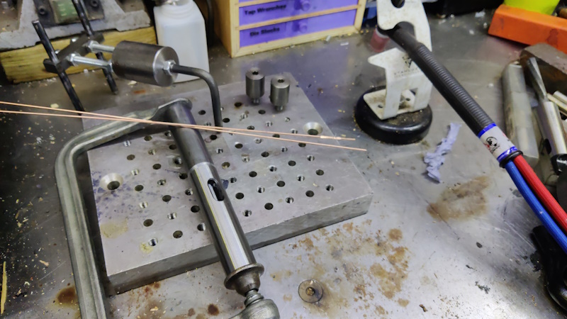
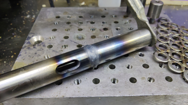
The first tack didn't go at all well, so I turned the Argon on (D'Oh!) and tried again and things went much better second time round. It was quite awkward welding as I had to do it in small sections, but it's looking okay to me so far:
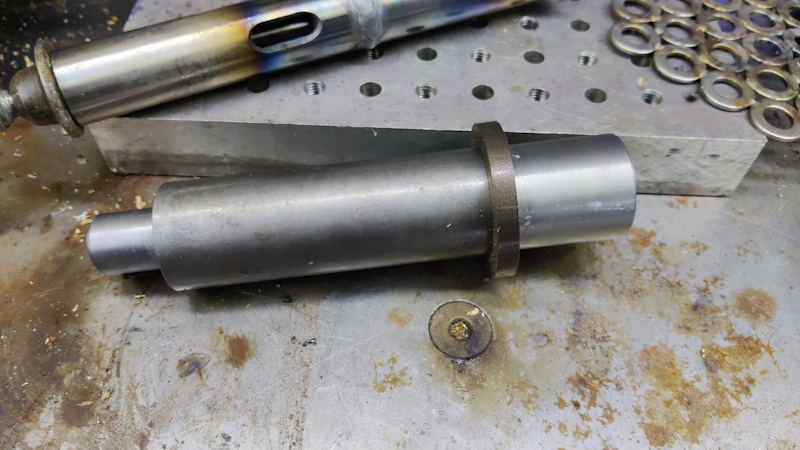
That was then left to cool down and by now I figured that the spindle bits were probably somewhere near hot/cold, so I went back into the house and quickly joined them together (with a bit of mallet-based persuasion for the last bit):
That's now ready for turning between centres, at which point I'll know how good the fit of the wider bit was. That larger diameter bit is only forming a register against which a chuck would rest, so it's not going to be put under much strain once in service, so it should be fine.
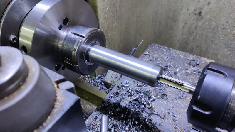
Before turning between centres, I went back to the tailstock spindle. I mounted it in the collet chuck and skimmed the outside diameter of the EN3B bit to make sure it was concentric and a smaller diameter than the adapter bit. I then drilled out the hole to 8.5 mm and started tapping M10 left-hand:
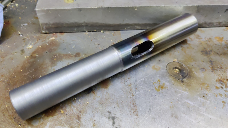
I went in far enough that I felt sure the thread had started properly, then took the tailstock spindle out of the chuck, put it in the vice and finished tapping by hand. I was a bit nervous about breaking the tap as I didn't have a spare of either the tap or the Morse taper adapter. Thankfully all went well and the tailstock spindle is (almost) done:
The last job on that will be to mill a slot in the EN3B bit for a pin that will stop it from rotating (when drilling or whatever).
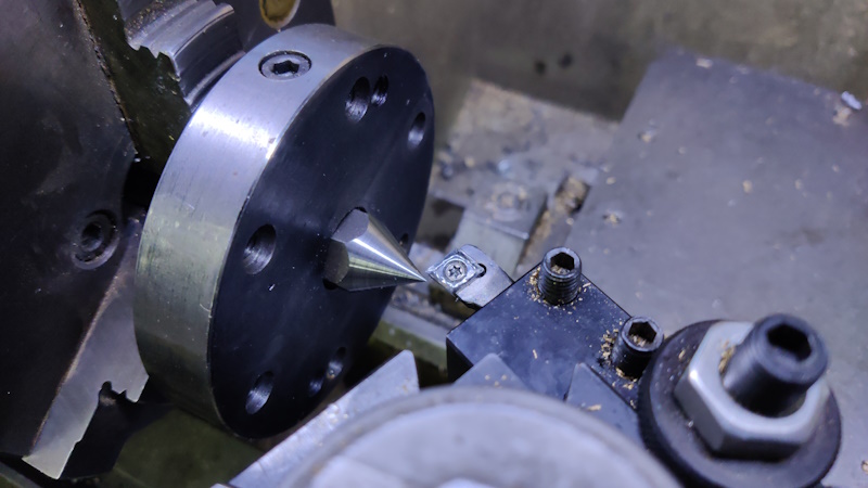
Now back to the headstock spindle. I put the three-jaw chuck back on the lathe, mounted a soft centre and took a very light cut to make sure it was definitely running true to the machine:
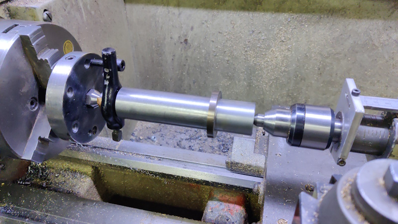
The spindle could then be mounted between centres ready for turning.
That felt like a good place to stop for the evening: tomorrow I'll get on with turning the spindle to size (whatever that size may be!)
Page 4 of 43
This website is free and ad-free, but costs me money to run. If you'd like to support this site, please consider making a small donation or sending me a message to let me know what you liked or found useful.

 Return to main project page