Woodturning Lathe Build Process
Page 5 of 43
Posted 10th February 2024
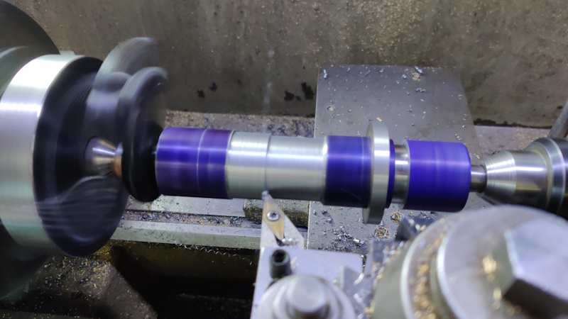
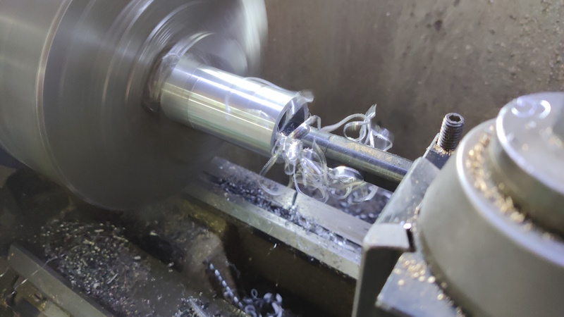
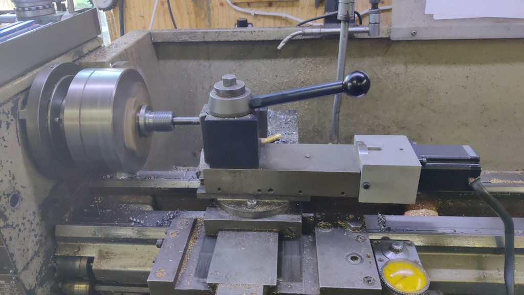
Turning the spindle took a lot longer than I expected. We left the "action" yesterday with the spindle mounted between centres on the lathe. I started by roughing out the shape of the spindle. Here's a blurry action shot:
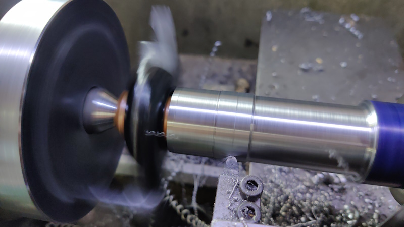
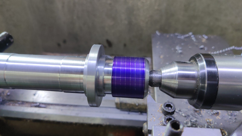
When the shape was roughed out, I swapped to a high-speed steel tool with a rounded profile. This tool can take extremely fine cuts. I used this to bring the two bearing surfaces to size (finishing one before starting the next):
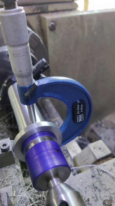
As I approached the final dimension, I was checking after each cut. I had the top slide set at about 5.75° to the axis of the lathe, which results in a 10:1 ratio of top slide feed to in-feed. That means that moving the top slide forward 0.02 mm moves the cutter forward about 0.002 mm. Being able to do that is very handy when you're creeping up on a critical dimension (as long as the tool can take fine cuts, which this one can).
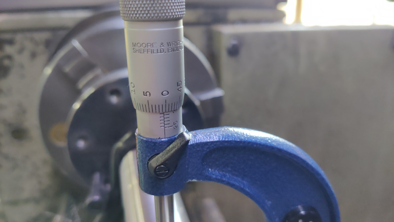
The reference book I was using suggested the shaft size for a 30 mm bearing should be between 30.002 and 30.011 mm. This was the final measurement on one of the registers:
At that point I just had to hope that I'd done it (and measured it) right and that all would be well when the bearings were fitted.
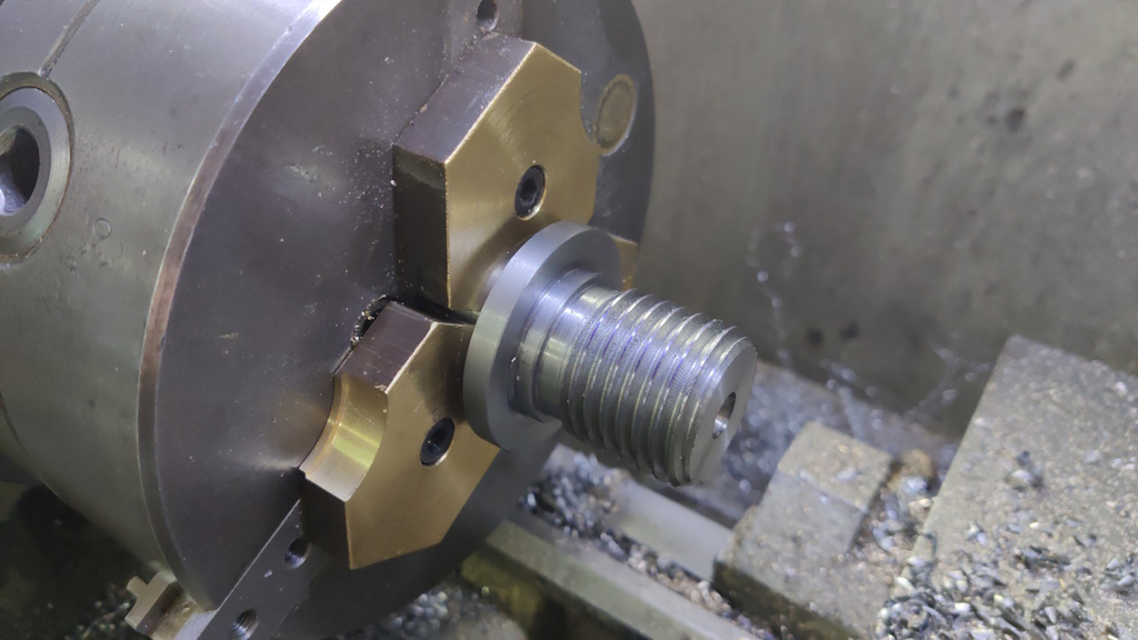
Next up was the thread for the chuck. I've never cut a thread as coarse as 3.5 mm pitch and I've got nothing to check it with, so I'll just have to hope it turns out okay.
After rearranging the change gears on the lathe (I can only go up to 2 mm pitch with the "standard" arrangement), I did a very light cut to check the pitch came out okay:
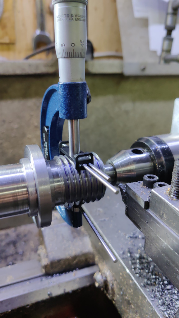
I then kept taking light passes (feeding in with the top slide, which was set at 60°) until the over-wires measurement was slightly under nominal for M33×3.5:
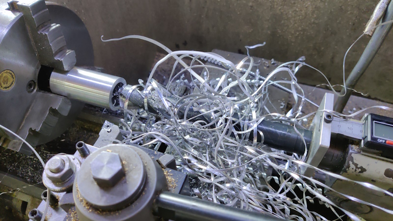
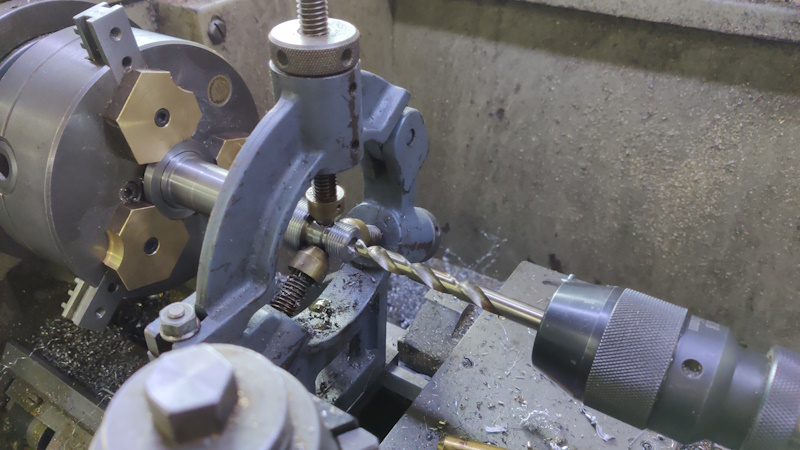
The spindle could then be removed from the centres. There's still lots to do, but nothing that could be done with that set-up. With the spindle roughed out, I could measure the distance that would be between the inside faces of the two bearings. A spacer between them will make it much easier to assemble, so I rummaged around for a while and found a bit of aluminium that was (just) big enough. After facing it in the lathe, I drilled a hole, going up through the sizes until I reached my biggest (25 mm) drill bit and reminding myself of why I hate turning aluminium:
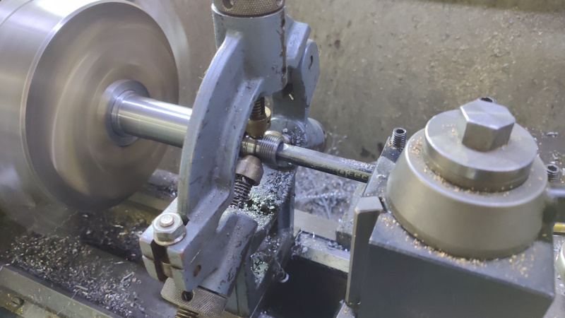
Once I'd run out of drill bits, I used a boring bar to enlarge the hole to a bit over 30 mm. The dimension isn't critical as long as it goes over the bearing surfaces.
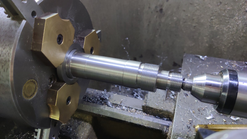
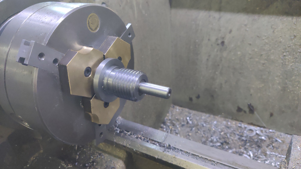
That piece was parted off to length and then it was back to the spindle. I fitted my soft jaws to the chuck and bored a pocket in them of the right size to hold the widest diameter of the spindle. I then mounted the spindle with the nose facing into the chuck and turned a couple of threaded bits on the outer end.
The left hand one of those will be for a pair of nuts to hold the spindle into the headstock. The right-hand one will hold the pulley in place. Given that I'll be making the nuts, I decided to make both of them 1.5 mm pitch as I have some insert tooling for cutting 1.5 mm pitch threads.
With the threads cut, I fitted the fixed steady, running on the surface that the pulley will sit on (I didn't want to run it on the bearing surfaces in case it damaged them). I could then remove the tailstock centre support and drill a bit over half way through the spindle. I drilled 10 mm then 13 mm and then bored to 14.6 mm (or thereabouts), which is a little over the small-end diameter of a Morse Taper 2.
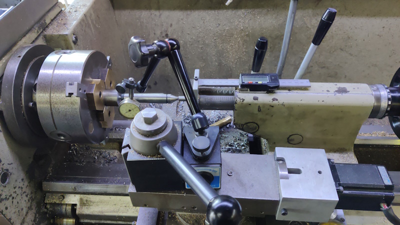
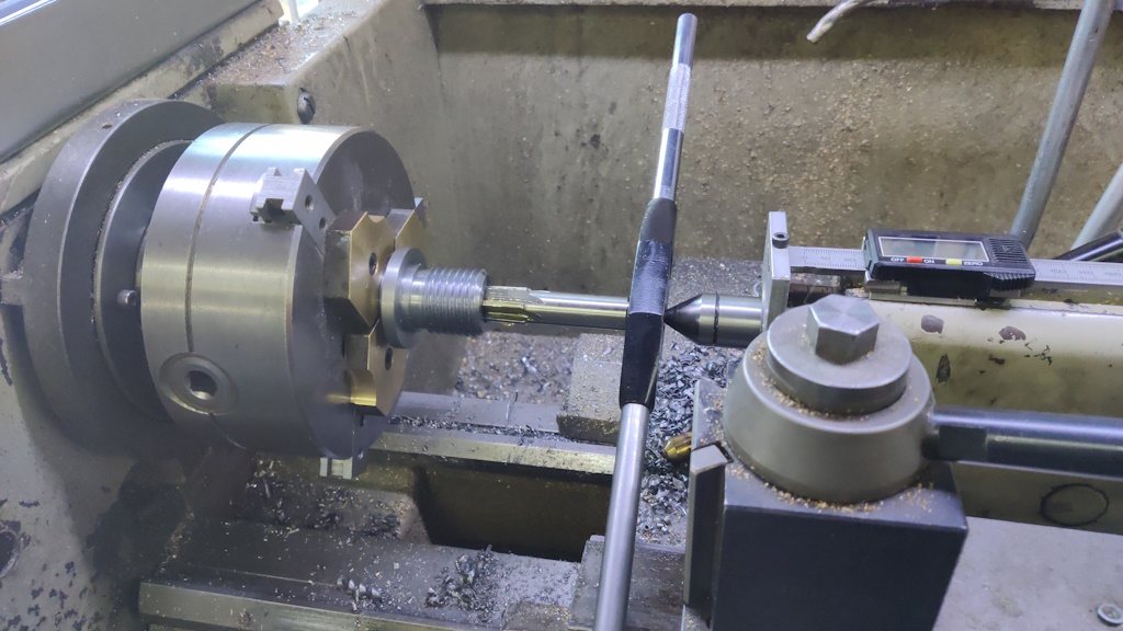
The next job was to align the top slide to the correct taper for MT2. While I had the soft jaws in the chuck, I mounted a bit of scrap and turned a short centre on the end. I could then mount a bit of MT2 tooling between headstock and tailstock and use it to align the top slide. Before doing that, I swapped the top-slide hand-wheel for my home-made top-slide motor (which uses a DivisionMaster controller configured such that 1° is 1 mm). The top-slide motor allows very fine control of position and very smooth motion, which is nice when cutting tapers as it leaves a good finish.
There was an intermission during this period where I dropped the Woodruff key that connects the top slide leadscrew to the handle and spent about an hour rummaging through swarf to try to find it again.
With the top slide aligned, the spindle could be mounted in the soft jaws (which were machined in place to have a 30 mm bore: machining in place guarantees that they'll hold the spindle concentric with the bearing surface).
After drilling and boring to 14.6 mm as before, I used the top slide motor to bore the Morse Taper, gradually increasing diameter until the outside diameter was about right according to the reference dimensions.
I happen to have a Morse Taper 2 reamer, so I pushed that into the spindle and turned it a couple of times as I figured it would probably improve the accuracy compared to my top slide alignment attempt.
I then grabbed a bit of Morse Taper 2 tooling I had and shoved it into the spindle. It didn't want to come out again, which I saw as a good sign!
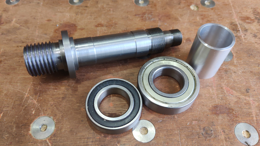
Once the MT2 tool was removed (with a bit of 12 mm bar inserted from the rear of the spindle and hit with a hammer), it was ready for assembly and finally finding out how I did with the bearing surfaces:
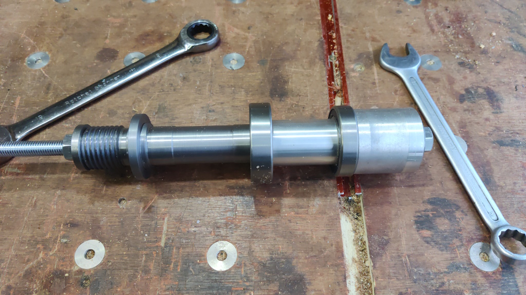
I don't have a press of any kind, so the only way I could think of pushing the bearings on (remember that the bearing surfaces were turned to interference fits) was with a bit of M12 threaded rod and a few hastily turned washers / spacers:
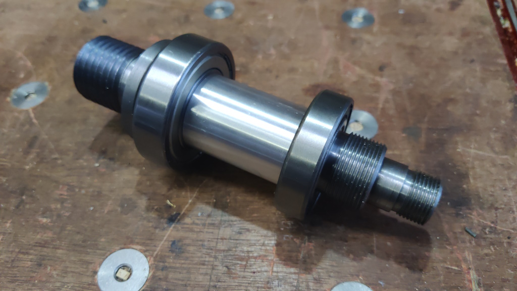
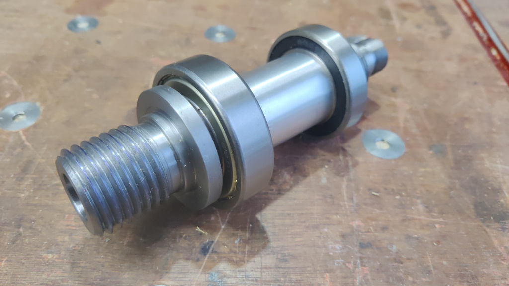
I was extremely relieved when the bearings slid home!
That's it for today. I need to have a hard think about how on earth I'm going to make headstock and a tailstock and how I'm going to get the requisite holes in them aligned. That feels like it's going to be quite a challenge, especially given the amount things are likely to distort when I weld them together.
Page 5 of 43
This website is free and ad-free, but costs me money to run. If you'd like to support this site, please consider making a small donation or sending me a message to let me know what you liked or found useful.

 Return to main project page