Harrison M250 Modifications and Tooling
Having had my mini-lathe for about 6 years and having used it fairly extensively (for a home workshop), I had started to find I was regularly trying to make parts that were too big for the mini-lathe to comfortably handle (for example, my flywheel fly-cutter). The mini-lathe then developed an electronic fault and would no longer run (I eventually traced this to a faulty capacitor on the main circuit board so it's working again now).
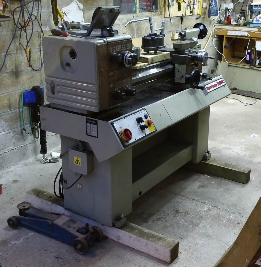
The combination of lack of capacity and a (temporarily) faulty mini-lathe spurred me on to start looking at alternative options. I considered getting a new Chester or Warco lathe but after chatting with a few more experienced machinists, I decided to to be brave and look at a second-hand machine. After much browsing of lathes.co.uk and reading various on-line forums, I settled on a Harrison; either an M250 or an M300. With a relatively limited budget, the condition of the M250s I found available and affordable was generally better than that of the M300s so in November 2017 I ended up with a 30 year old M250.
Criteria for Choosing a Lathe
For reference, the criteria I used for selecting a lathe were (from memory and in no particular order):
- Floor standing.
- Centre height over top-slide sufficient to accept 12 mm or (better) 16 mm tools (to allow tools to stick further out from the toolpost and hence give more clearance to the tailstock centre etc).
- Able to swing 250 mm (a bit under 10") such that I could relatively comfortably work on 200 mm parts when required.
- Non-threaded chuck mount (preferably cam-lock, which the Harrison lathes are, but flange-mount
okay). This makes chuck changes quick and straightforward and also allows the lathe to be
run backwards without risk of the chuck unscrewing. Example uses for this:
- Upside-down threading tools, which allows threading away from the chuck (less risk of crashing);
- Parting with an upside tool (reducing the need for an rear tool post);
- Upside-down brass tools can be nice for turning brass: the fine swarf that's generated gets fired down into the tray rather than up into your face;
- Cutting tapers (e.g. for soft centres) with the top slide in a more convenient position (with a standard orientation tool): you can cut on the far side of the work piece;
- Less significantly, it also gives more confidence when cutting imperial threads: the lead-screw needs to stay engaged so you run the lathe backwards to get back to the start of the thread. In theory there shouldn't be any significant forces trying to unscrew the chuck, but a non-threaded chuck mount gives more confidence, especially with large work pieces with a lot of inertia.
- As big as possible spindle bore.
- Metric dials and lead-screw (the latter especially makes threading a lot easier as a thread dial indicator can be used for metric threads).
- Powered fine feed, independent of lead-screw: this decreases wear on the lead-screw and (compared to the mini-lathe) means that you don't have to change gears between fine feed and gear cutting.
- Powered cross-feed: I've never mastered getting a really good finish when turning hand-wheels by hand. Having a powered cross-feed allows me to get really good finishes on facing cuts very easily.
- Gearbox to enable quick selection of most common metric threads.
- Hardened bed.
- In an ideal world, a method of accurately positioning the carriage. In practice, this doesn't seem to be a standard feature of many lathes (hence my addition of the leadscrew handwheel on the mini-lathe). I had initially resigned myself to the idea that I'd fit a digital read-out to the lathe, but in the end the lathe I bought came with an analogue travel dial indicator (pictured below) and I use this as my main (or maybe even sole) method of X-axis positioning.
There were probably others as well that I've forgotten!
Distance between centres wasn't particularly a priority. I wanted a longer centre distance than the mini-lathe such that I didn't have to take the tailstock off the bed so much, but any lathe with a 250 mm swing has a centre distance that's more than I'm likely to use.
A few websites I've seen (including lathes.co.uk) have listed a T-slotted cross-slide as an essential feature but this didn't make it onto my list of requirements. Having a reversible spindle means that a rear toolpost isn't essential (and there are threaded holes that can be used to mount one if required) and I am unlikely to do much milling in the lathe given that I have a milling machine. Anything else that I want to mount on the cross-slide can be mounted using a custom mount attached to the various threaded holes on the cross-slide. T-slots would add little in terms of capability but would fill up with swarf and be a pain to keep clean.
Another feature listed as important on lathes.co.uk is a back gear (which should be interpreted as a slow speed - the back gear is the Myford implementation), which is covered with a good speed range in the gearbox. The website also suggests the importance of a spindle lock for chuck removal, but this seems to only be relevant for lathes with the inferior threaded chuck mount. On the Harrison M250, I can set the speed to 40 rpm, which makes the spindle very hard to turn and meets most requirements I'm likely to have of a "spindle lock".
Harrison M250
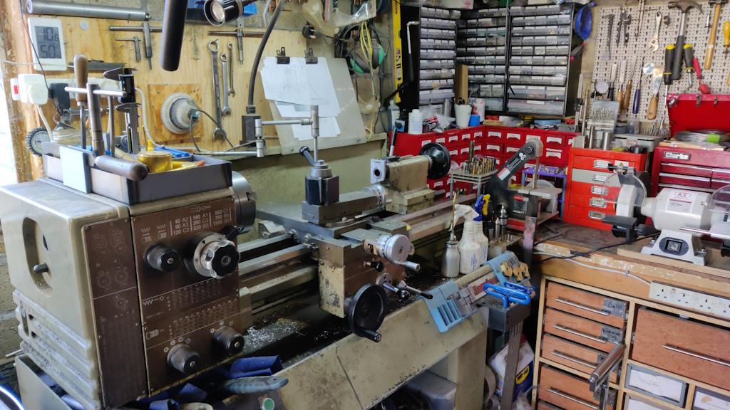
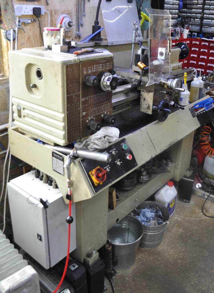
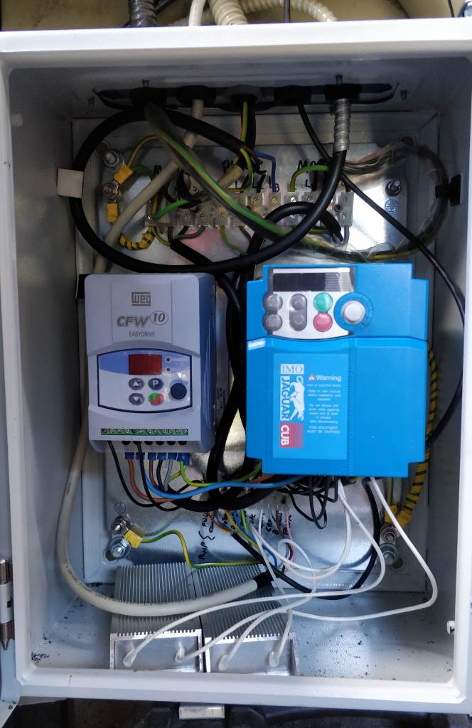
The Harrison M250 has a centre height of 145 mm; mine is the long-bed version with 750 mm (30") between centres. It has an induction-hardened bed, which is 190 mm wide (greater than the centre height, hence giving good robustness for its size). It has nine speeds from 40 rpm to 1500 rpm with a three-phase motor, which I've switched from star to delta configuration (to reduce the voltage needed) and connected to an inverter to provide variable-speed capability and (more importantly) to allow running from a single-phase supply. As well as the one I bought for the purpose of running the lathe, I had a fairly low-power inverter lying in a cupboard. I used this to provide power to the suds pump fitted to the rear of the machine. In practice I rarely use this, preferring to use a wash bottle or a brush to apply coolant.
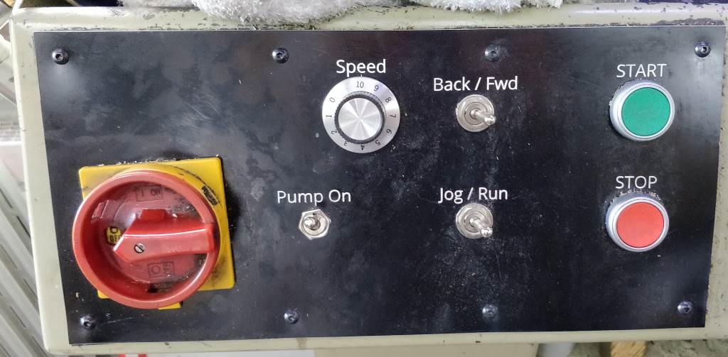
These pictures show the bulk of the three-phase to single-phase conversion work. The top photo shows the internals of the cabinet I fitted on the end of the lathe and the lower one shows the new console that connects up to the inverters to allow the lathe to be controlled. The console was laser cut and engraved: I bought a job lot of acrylic of various different types and colours on ebay and then used a laser cutter/engraver at my work to produce this and a few other parts. Near the bottom of this page (or click here), you can see a picture of what the lathe looked like originally for comparison.
The Spindle
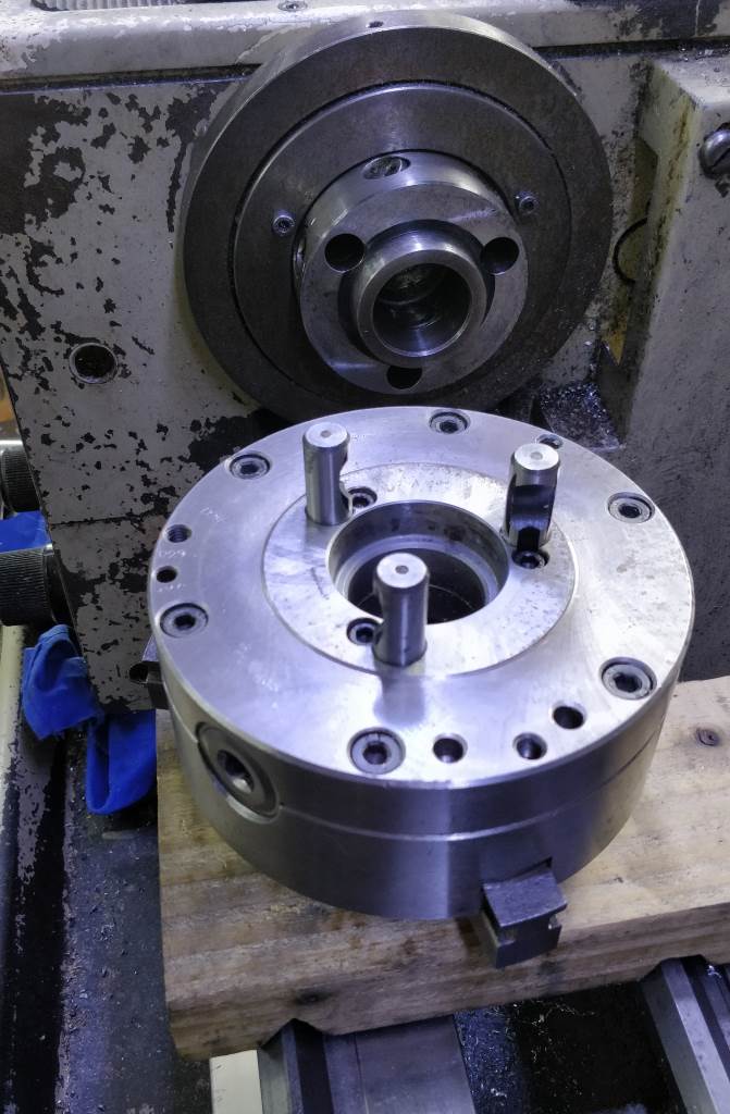
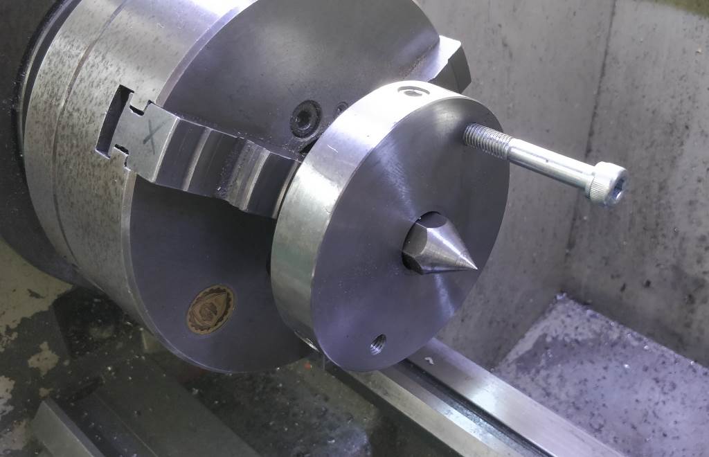
The spindle has a D1-3 cam-lock nose and a 35 mm spindle bore with a number 4.5 Morse taper. This isn't ideal as adaptors are very hard to come by - I made my own to take it down to MT3. Having said that, it hasn't really caused me too much of a problem as I rarely use the spindle taper: when turning between centres I tend to use a soft centre (turned from some 19 mm hex bar with a drive-plate made from a 20 mm long piece of 100 mm diameter mild steel) held in the chuck. This is turned in place immediately prior to use so is as accurate or better than a spindle-taper-mounted centre. The lathe's 750 mm centre distance means that reduction in centre distance resulting from the presence of the chuck is largely irrelevant.
Workholding
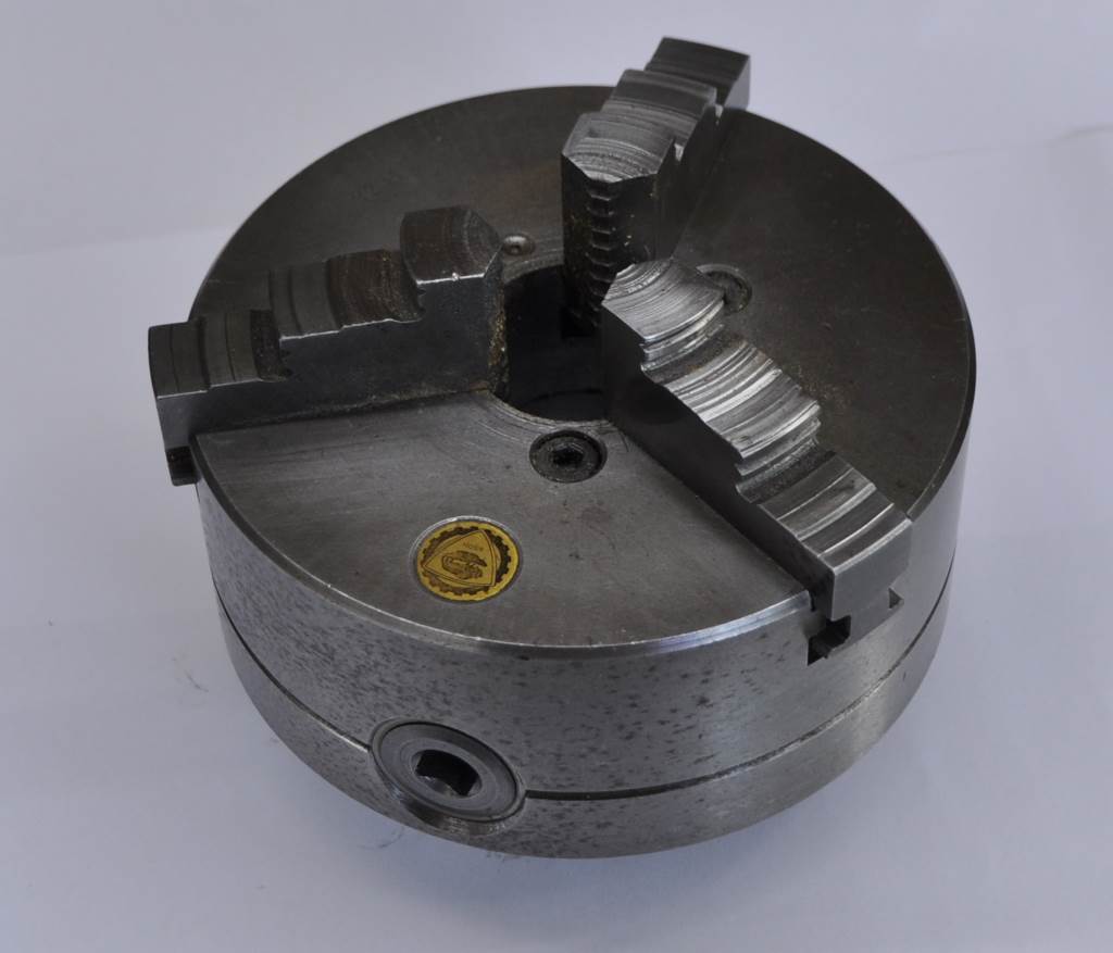
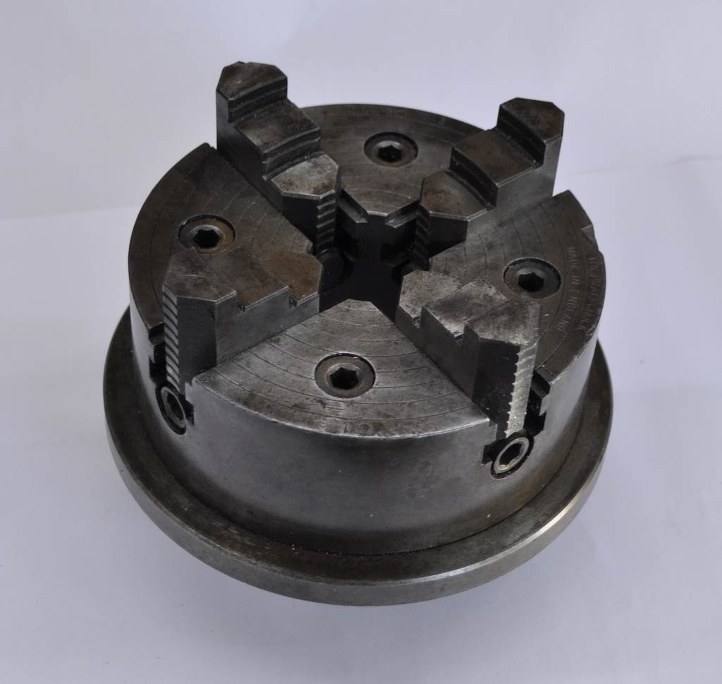
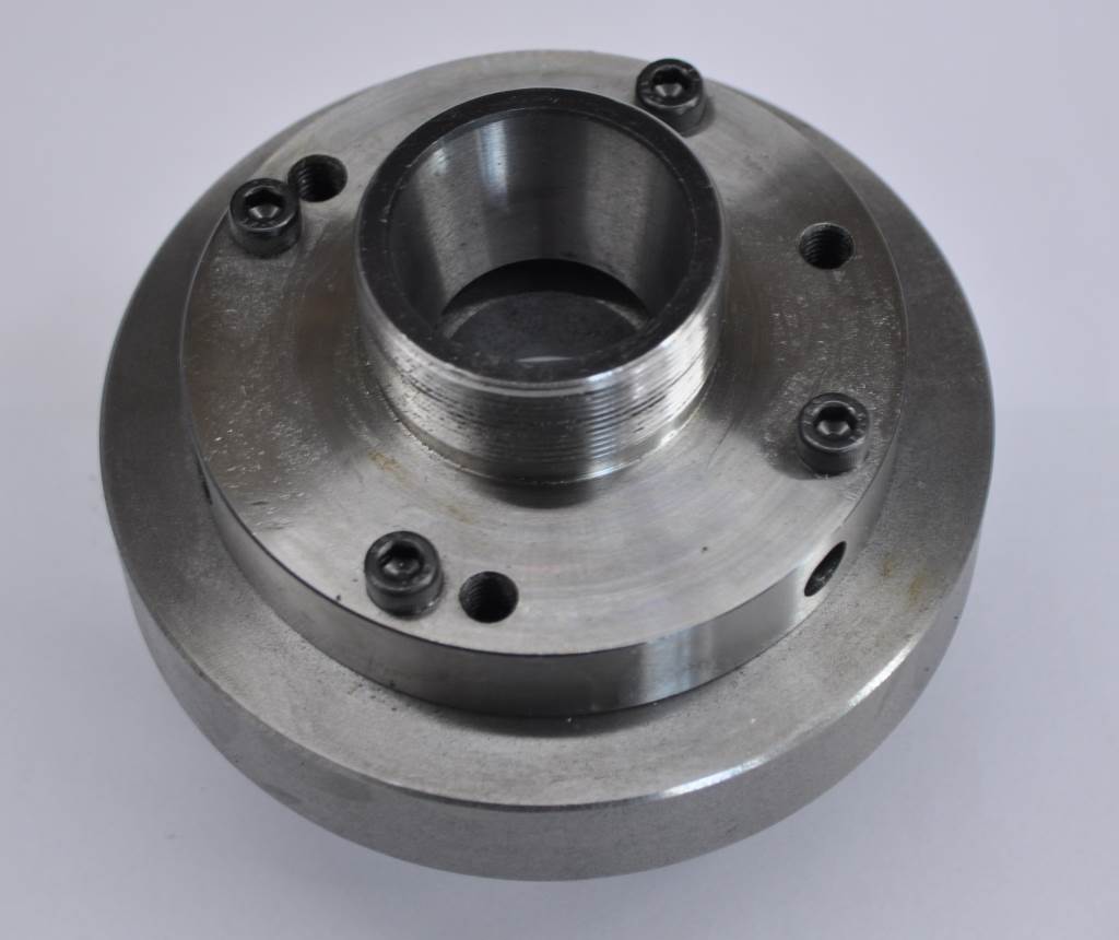
The machine I bought came with a (probably original) three-jaw chuck and a four-jaw chuck on a backplate. I bought a spare (un-machined) D1-3 backplate and fitted an ER40 collet chuck so I have three options for chuck-mounting available to me. I have also bought a 10.5" (266 mm) faceplate.
No doubt as a result of the age of the machine I was able to afford, the bed is fairly well worn. If I adjust the carriage such that it is a very good running fit on the bed in the area most commonly used, then it gets very stiff and hard to use at the far end of the bed. For now, I've adopted a compromise fit which is working well but I guess this limits the accuracy on long lengths a little. Carefully adjusted for the tighter fit it turns to within 3 μm over circa 100 mm, which is probably sufficient for my use for now. I'm still gradually exploring the limitations of the machine in terms of accuracy, so I guess we'll see whether other issues present themselves.
Analogue Travel Dial Indicator
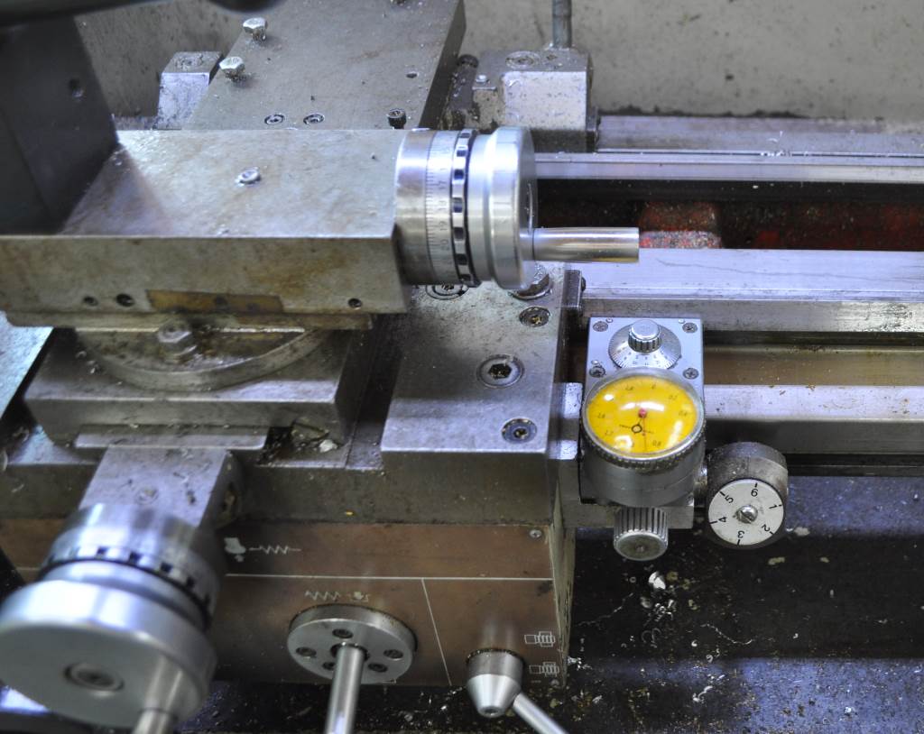
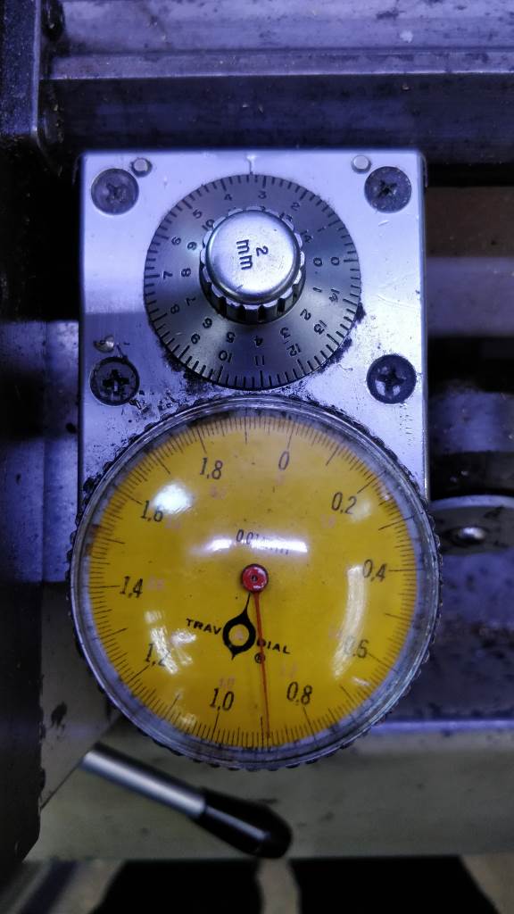
The lathe came with a dial indicator for measuring carriage position. This measures movement along the bed in 0.01 mm increments up to a maximum of 150 mm. Beyond this distance the measurement wraps, but it's fairly easy to keep track of which multiple of 150 mm you're on in the rare situations when turning something that long that requires accurate length control. I haven't checked the accuracy of the travel dial specifically but parts made using it have all been to the required specification. If I ever sell the M250 and buy a different lathe, the travel dial indicator will be removed and fitted to the new lathe: it's fantastic!
Height of the Lathe
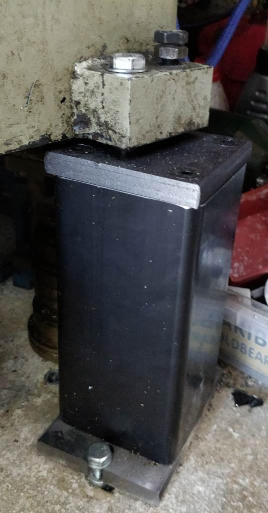
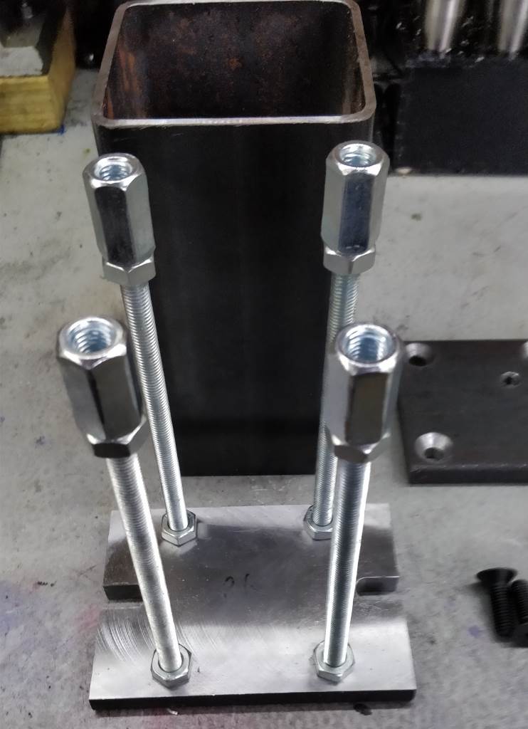
The M250 is designed for people significantly shorter than me. To get the lathe up to a height where the cross-slide handwheel is at my elbow height required it to be raised onto some home-made risers. The second photo on this page shows the risers fitted underneath the lathe. The left-hand photo above shows a close up of a riser under one of the tailstock feet and the right-hand photo shows a riser partially assembled. The box section steel is 100 mm across with a 4 mm wall section. The four box section lengths were each mounted in the vice on the milling machine and fly-cut square such that they were 202 mm long. The top and bottom plates were made from 100 mm × 15 mm hot rolled steel. One side of each part was fly-cut to remove the rough finish and take the thickness down to 14 mm, resulting in an overall height of 230 mm. Four 10 mm countersunk holes were drilled in the corners of the top plate and four M10 threaded holes tapped in the corners of the base plate. The base plate had a slot milled at each end for the rawlbolts that hold the risers to the floor and the top plate had an M12 hole added for bolting to the lathe feet.
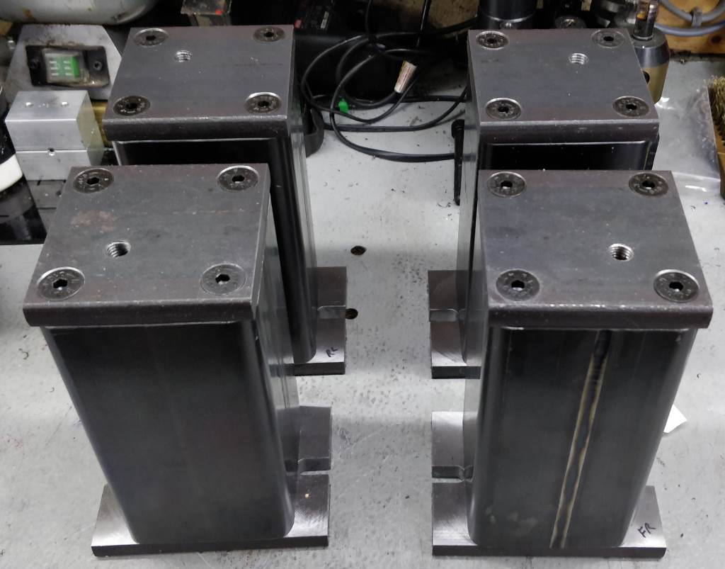
This image shows all of the risers prior to fitting under the lathe. Hopefully this photo in combination with the ones above show how the risers fit together and how the lathe attaches to them.
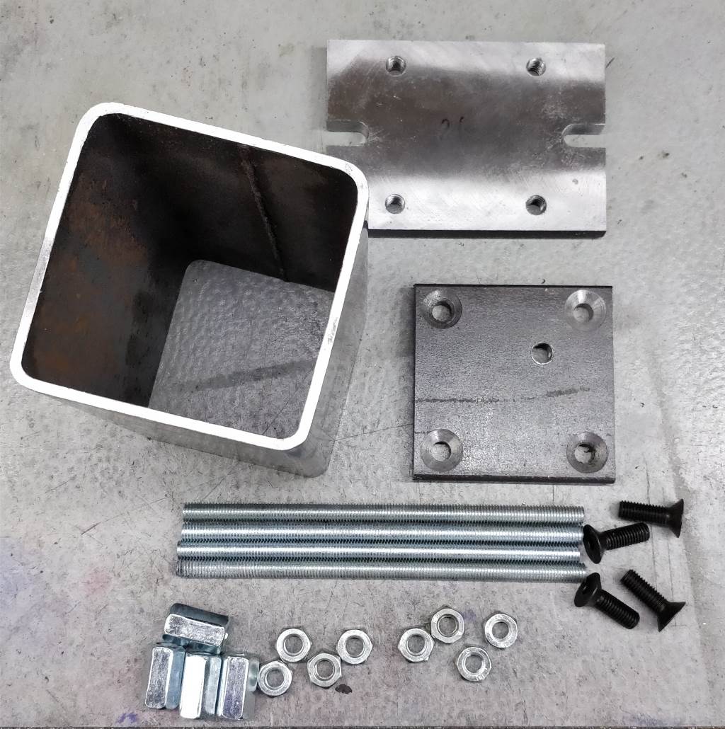
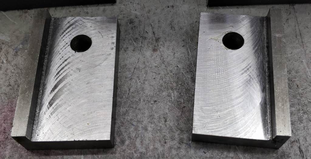
The left-hand image above shows all of the parts that make up a single riser. This, in combination with the other photos should make it clear how they go together. The right-hand photo shows some additional spacers that were made to go between the lathe feet and the risers at the headstock end. The floor of my workshop isn't precisely level and to get the lathe level requires more adjustment than is available in the adjustment screws in the lathe feet. I considered making the headstock risers longer than the tailstock ones, but decided to make up the difference with additional spacers instead - this means that if I move house I shouldn't have to remake the risers. The ridge that can be seen in the spacer pieces is there to butt against the side of the lathe feet and stop the spacers wandering around while the screws are tightened.
Other Issues
One limitation of the lathe that I hadn't foreseen is the lack of a travelling steady. There are mounting points for one but the machine I bought didn't come with one and it has proven very difficult to find one for sale for this machine (travelling steadies for the M300 seem readily available). I had never felt the need for one in the turning I did on the mini-lathe, but the increased bed length has meant that I am finding myself turning longer parts on the M250 and in a few instances a travelling steady would have been beneficial.
Moving the Lathe Around
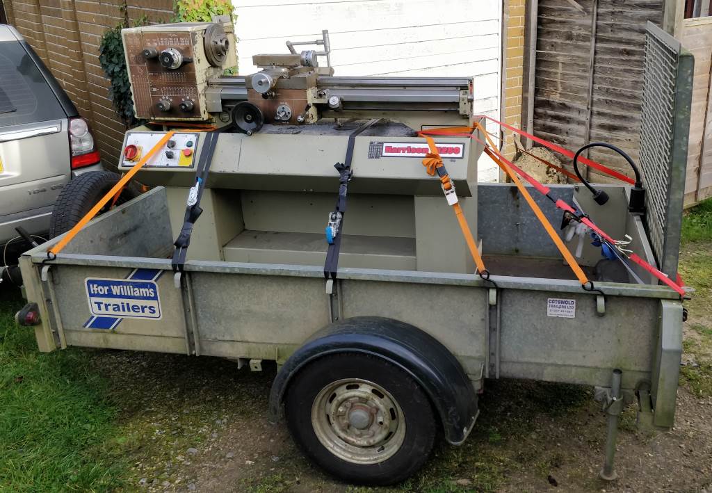
The lathe weighs about 500 kg. This makes it a lot more difficult to move around than the mini-lathe! The ebay seller that I bought it from had a fork-lift truck, so moving it around at that end was relatively easy. I hired a trailer to bring it up to my house and spent a lot of time preparing for the move. From information gathered from the manual, I knew the distance between the mounting screws on the lathe feet. I also knew the size of the trailer I was hiring, so I got some substantial pieces of wood the same width as the inside of the trailer and drilled holes at the right spacing for the lathe feet. At the seller's workshop, I bolted these pieces of wood onto the bottom of the lathe. This increases the back-to-front width of the lathe at the bottom and makes it much less likely to topple-over (which would have been a disaster). I used some short lengths of scaffolding bar under the ways of the bed (with some wood to protect the lead-screw and fine feed shaft) and lifting straps to raise the lathe with the fork-lift truck and load it onto the trailer.
My garage used to have an asbestos roof resting on angle iron cross-beams. There were a lot of holes in the asbestos panels so shortly after moving in (and long before buying any metalworking equipment!) I took the asbestos off and replaced the roof with a wood-framed construction with EPDM rubber on top. When I did this, I decided to leave the angle iron in place. This massively simplified the process of getting the lathe into my garage: I reversed the trailer into the garage and then used a chain hoist attached to one of the angle-iron beams to lift the lathe straight up (again using the scaffold poles and lifting straps). Once it was a couple of centimetres off the bed of the trailer, I pulled the trailer out from underneath it and lowered the lathe to the floor. As I was lifting from the centre of the angle-iron (deflection is a distance-cubed relationship), the angle-iron bowed significantly during this process, but it went back to where it had started so presumably didn't reach the elastic limit. Later lifts were over near the wall of the garage so it wasn't a concern. The lathe then stayed in the middle of the garage for a few weeks while I rewired the motors and added the box with the inverters.
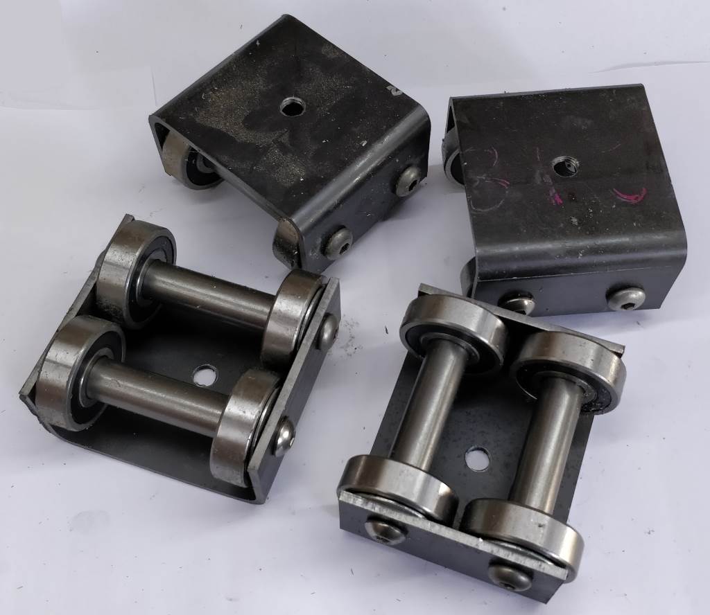
Moving the lathe around the garage was a little more difficult than getting it in there in the first place. I made four castors out of the left-over box section steel and some 20×52×15 mm bearings. These were bolted to the bottom of the lathe (after lifting each end in turn with the chain hoist) and then the lathe could be wheeled to the other end of the garage. This would have worked a lot better and required a lot less tweaking if the castors at one end had been made in such a way they could rotate. Nevertheless, eventually I got the lathe to roughly the right place. Getting it onto the risers and getting the risers bolted down was a bit of an ordeal involving lifting each end a bit at a time and it probably would have been a lot better to hire an engine hoist or something like that!
M250 Pages
- Hex Key Rack: A rack to keep hex keys at hand.
- Hex Key Rack Mk2: 3D printed hex key rack.
- Hex Soft Jaws: Soft jaws for short-piece turning.
- Holders for Small Tools: Using $dim{8}$ tools in the big tool post.
- M250 Back Stop: A back-stop for consistent positioning of parts in the chuck.
- QCTP Tool Holders: Lots of QCTP tool holders.
- Small Modifications: A few small tools/modifications that didn't seem worth putting on a page of their own.
- Storage for Bar Stock: Storing long bar stock without taking up too much of the limited workshop space.
- Storage for MT3 Tooling: Convenient storage for tooling that fits in the tailstock taper.
- Tailstock DRO: Easy drill depth measurement.
- Tool Height Setting Gauge: Simple height setting for cutting tools.
- Top Slide Motor: Cutting tapers with a good finish.
- MT4.5 ER40 Collet Chuck: A collet chuck that can be mounted directly in the spindle of the lathe.
- Ball Turning Attachment: An attachment for turning spherical shapes with the lathe.
- Two Part Soft Jaws: Improved soft jaws.
This website is free and ad-free, but costs me money to run. If you'd like to support this site, please consider making a small donation or sending me a message to let me know what you liked or found useful.

