Heat Treatment Oven Build Process
Page 19 of 35
Posted 4th January 2025
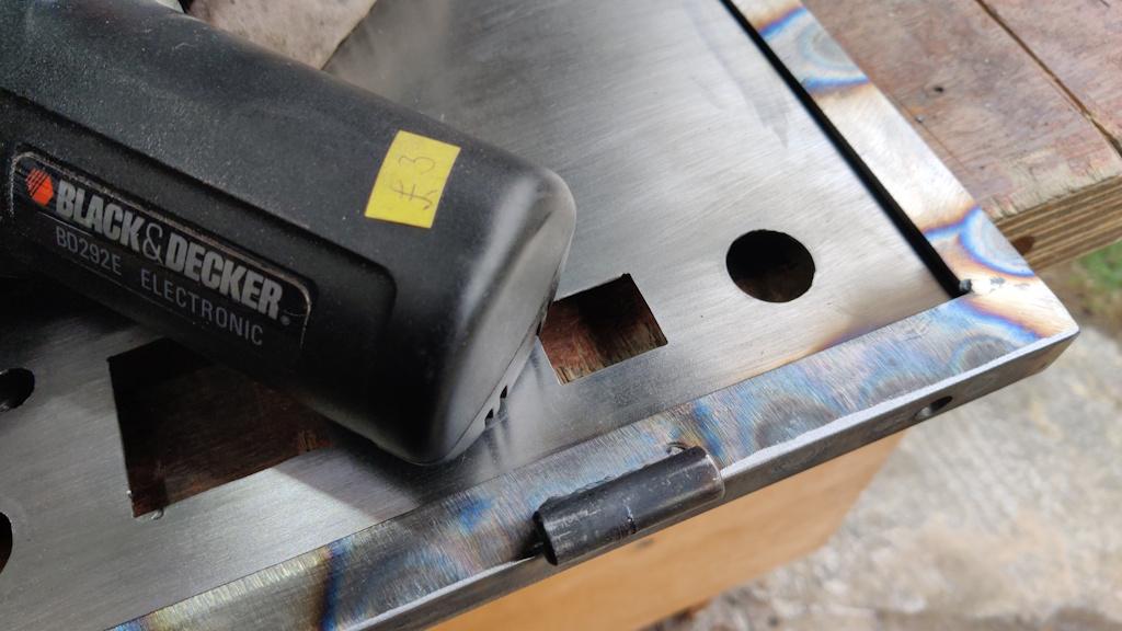
Today was another fairly slow day, but I got a few little jobs done. I'd noticed a bit of scarring on the hinge bodies, so I concluded that the slight roughness in the action was down to the moving bodies rubbing on the (relatively) stationery parts. To sort that out, I used a little bargain basement Black & Decker "power file" (narrow belt sander) to chamfer the edges a bit.
In hindsight, it would have been better to do this before fitting the hinges as I couldn't get the power file underneath the (integral) hinge pin on the hinge pieces attached to the body; I gave them a bit of a rub with some 80 grit wet-and-dry but it possibly could have done with a bit more.
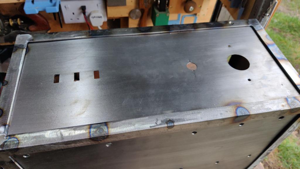
I made the decision overnight that I'm going to paint the cabinet before trying to wire it up. To that end I've ordered some metal paint (which will come towards the end of the week hopefully) and I need to make sure the cabinet is ready for painting. The last few minor jobs to do were some extra holes, first for a three-pin DIN socket that I'll use to connect the chamber door interlock:
That hole needed to be 17 mm and I didn't have an appropriate sized drill, so I used a step drill to drill 16 mm and then a deburring tool (something like this but with a 90° blade that cuts on both edges of sheet metal at the same time) to gradually open the hole out until the DIN socket fitted. I could then drill the two 3 mm holes either side for the mounting holes.
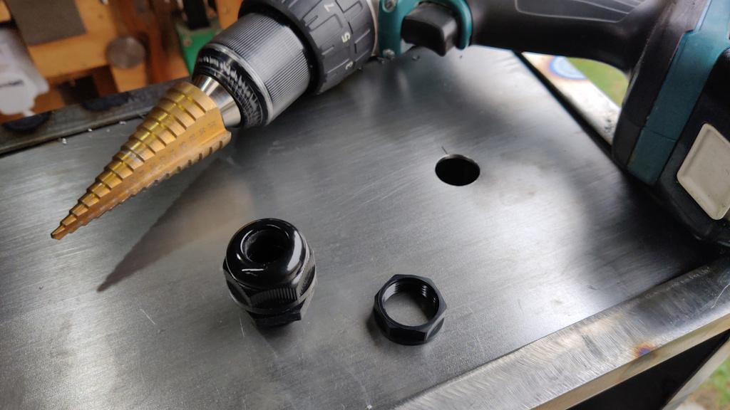
On the right-hand side of the cabinet, I used a step drill to drill a 20 mm hole for the grommet for the incoming power cable and another earthing screw attachment point (not visible in this photo):
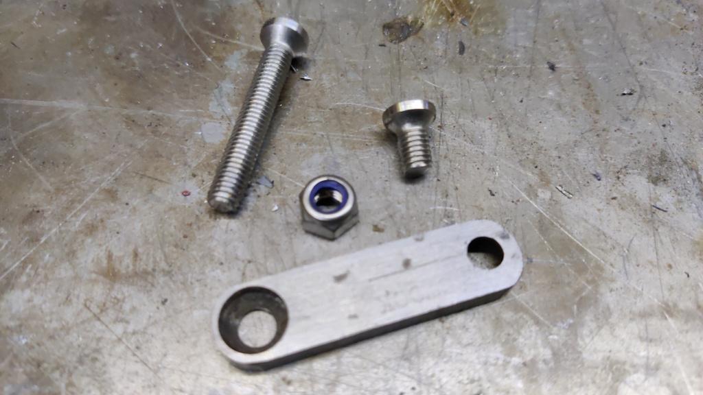
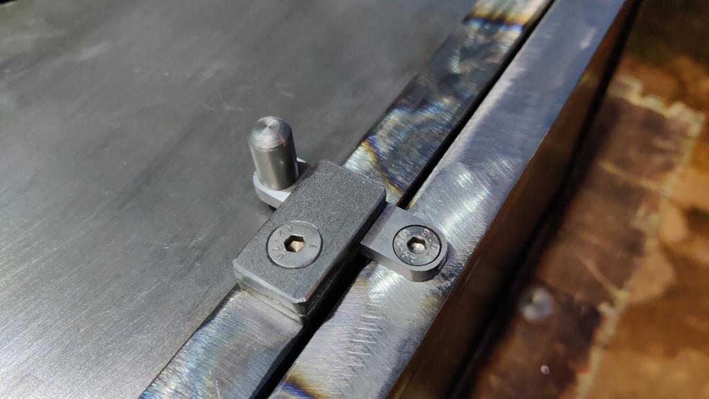
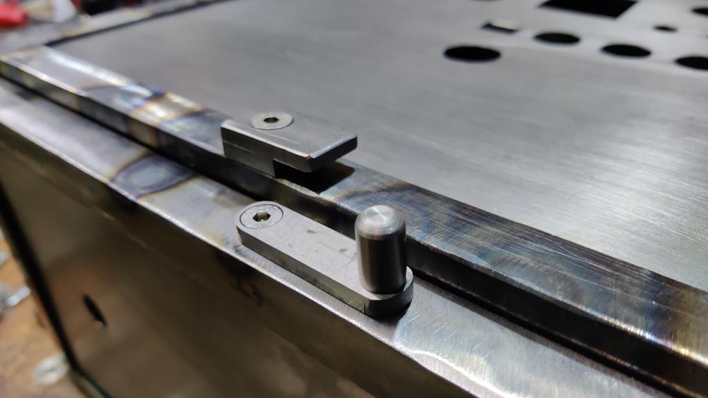
The last job I could think of for the cabinet was to make the door latch. This was made out of whatever bits I could find that looked about the right size. The rotating bit was made from some 12 mm × 5 mm steel, with a 6 mm hole drilled in each end and then both holes countersunk (from opposite sides) with a 10 mm diameter countersink. The countersink was used to drill a deep hole in the steel, so it's effectively counterbored and countersunk. The M6 countersunk screws used with it had their heads turned down to 10 mm (as I didn't want them to poke out the sides of the 12 mm steel). I also turned a simple knob out of 10 mm round bar (not shown in this photo);
The door part of the latch was just a couple of bits of appropriately sized steel I found. One was drilled and countersunk; the other (the spacer) already had an M10 hole in the middle, which is plenty big enough for the M6 screw to go through.
The moving part of the latch got screwed into the cabinet with a nyloc nut behind the weld nut so I could tighten it and then lock it in place at the point where the latch moved freely. The fixed part of the latch just got tightened directly to the door. This is what it looks like sealed...
... and open:
Fairly simple, but should do the job.
There has been some discussion going on on the MIG-welding forum about the painting process. I quite like the idea of using some sort of filler to fillet the joints between sheet metal and angle iron. On the outside it would clean up the look slightly. On the inside it would hide some of my more awful welds! The obvious option is car body filler but I'm a bit concerned that it might end up needing a lot and it could get quite expensive. An alternative would be exterior decorator's caulk, but I'm not sure how well it would stick to the steel. Any comments welcome...
Page 19 of 35
This website is free and ad-free, but costs me money to run. If you'd like to support this site, please consider making a small donation or sending me a message to let me know what you liked or found useful.

 Return to main project page