Heat Treatment Oven Build Process
Page 24 of 35
Posted 1st February 2025
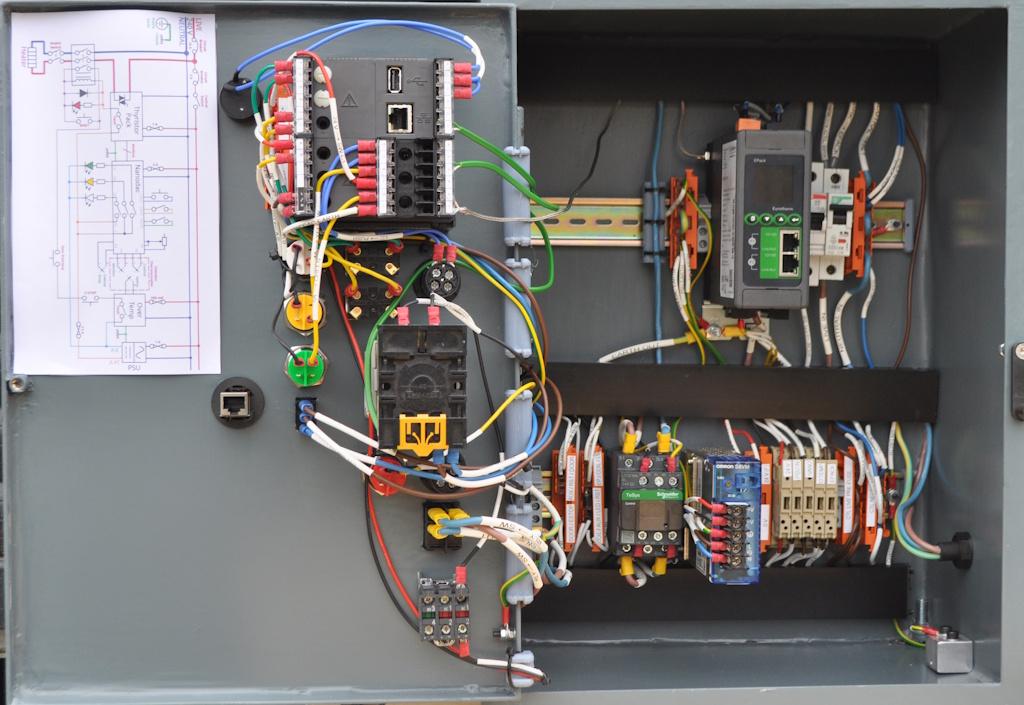
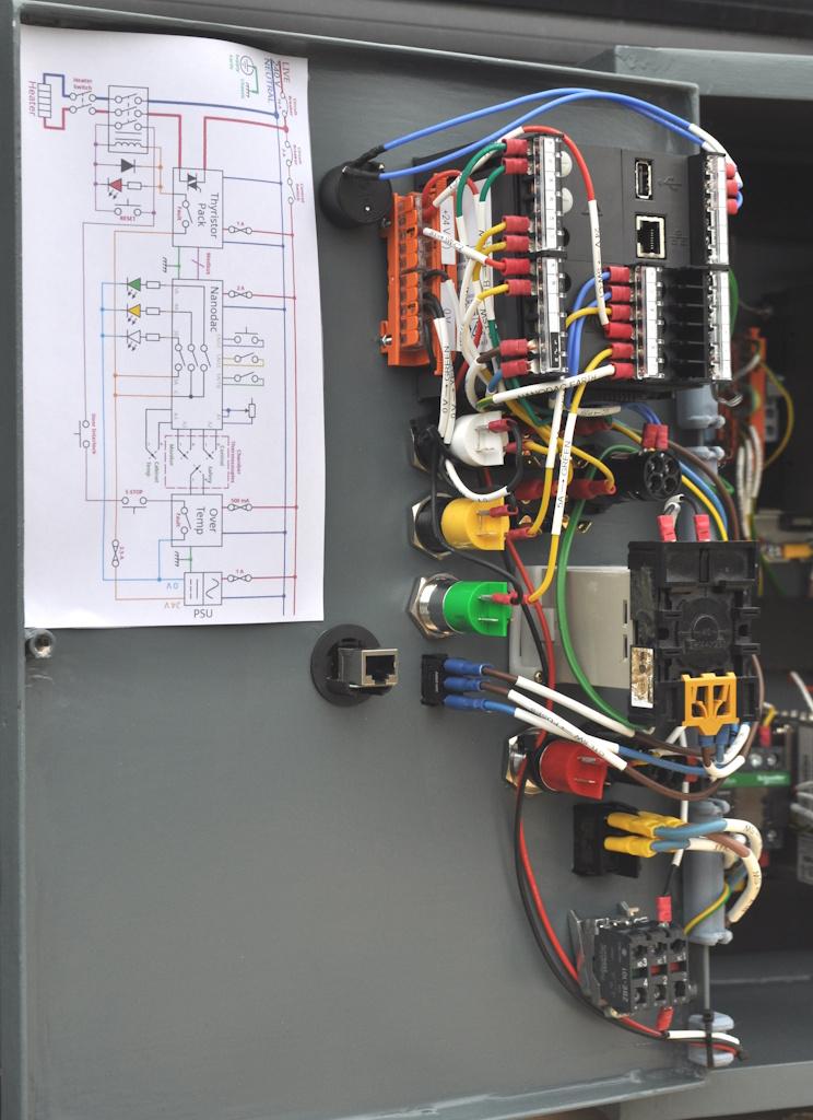
I've been fairly busy with things unrelated to this project for the last couple of weeks, but I have managed to spend some time in the evenings wiring up the control cabinet and I now feel that it's reasonably complete. This is what it looks like inside (with the two ethernet cables - the one from the Nanodac controller to the EPack thyristor module and the one from the EPack to the door - removed so the wiring behind can be seen more clearly):
It took a lot of thought to get everything laid out moderately neatly, but I'm pleased with the result. The photo makes it look like the cable trunking isn't parallel, but that's just a camera perspective effect.
I went a bit over the top on labelling and such-like. It's unlikely I'll revisit this wiring for a very long time, so I figured it would be helpful to have everything labelled clearly for whenever I do need to revisit it. Almost every wire has a heat shrink printed label on both ends showing where it's going from and to (the only exceptions are those that are so short or obvious that it's easy to trace the wire and even those have a label on one of the ends). The Wago connector blocks are also labelled with their purpose (with the exception of the ones at the top, which are quite obviously neutral and earth points).
After wiring it up, I went round with a multimeter and checked that any bit of metalwork (including the DIN rails) had a decent earth connection. The door has a dedicated earth wire, even though it's probably earthed perfectly well via the hinges. It's not obvious in the photo, but I added a couple of short bits of cable trunking on the left-hand side of the cabinet to route the wires from the trunking up to the door. Those bits of trunking have the covers cut a bit short (to allow the cables to 'escape') and the covers are cable tied in place (to stop the cables pulling the covers off when the door is closed).
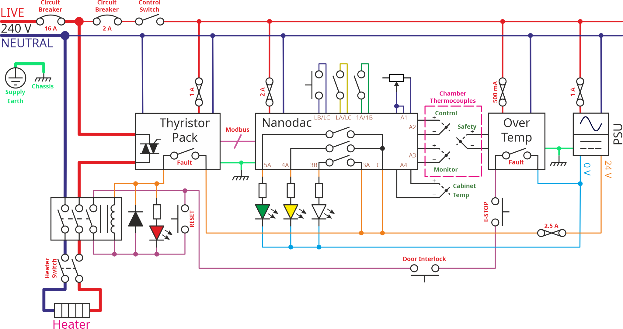
As you can see, I also printed out the wiring diagram and blue-tacked it into the door for future reference. That's an updated version of the wiring diagram, drawn after finishing wiring the cabinet. Inevitably the wiring differed a bit from the original plan: all the various cut-out switches (over temperature, emergency stop etc) have to be wired in series, but the order doesn't matter. When I wired the cabinet up, I wired them in the order that resulted in the neatest layout and it seemed sensible to update the drawing to match the actual wiring. While I was at it, I included the details of all the "user interface" (switches, lamps and a potentiometer) connections to the controller and also the fuse and circuit breaker ratings.
This is the updated schematic:
It's not as tidy as the previous version, but I think it's still perfectly readable.
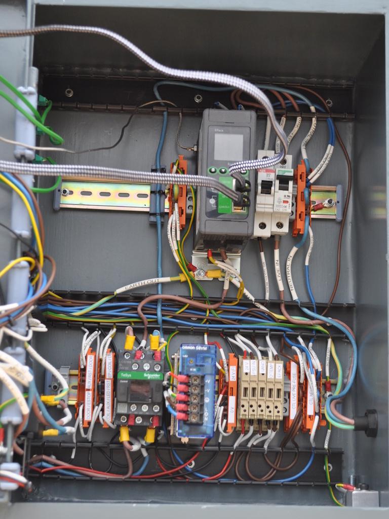
This is what the wiring looks like with the covers off the trunking (and with the ethernet cables now fitted):
Definitely a lot more messy, but not too bad considering how many connections there are.
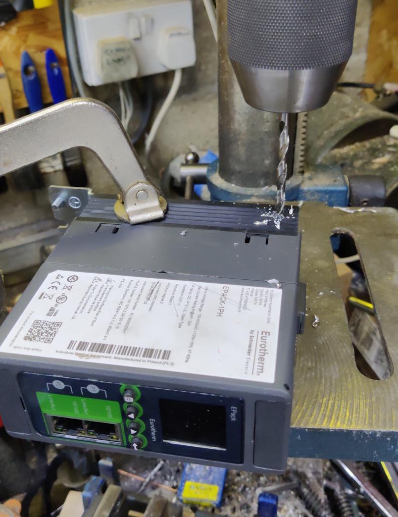
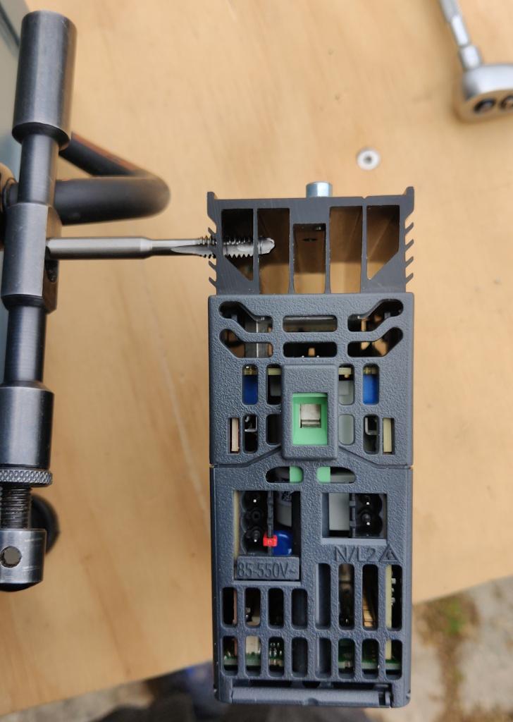
The eagle-eyed among you will notice a connection going into the top-left of the EPack thyristor module. That's a little thermocouple with a threaded fitting. I thought it would be interesting to have a temperature sensor showing how hot the control cabinet got. It's obviously going to be a lot cooler than the chamber and there probably isn't much point, but nevertheless it might be interesting to see if the electronic bits and bobs start getting hot. The EPack is likely to be the hottest thing in the box, so I decided to fit the thermocouple to its heatsink. I had a K-type thermocouple with a threaded end, so I decided to risk voiding the warranty (which I obviously don't have given that it was given to me for free!) by drilling a 5.1 mm hole in the heatsink...
... and then tapping it 1/4" UNC to match the antediluvian thread on the thermocouple:
This photo shows a bit of detail of the door wiring. The orange Wago block gives a central distribution point for 24 V and 0 V. It was an amazingly good fit in a little "indent" in the side of the Nanodac controller, so it seemed a good idea to tuck it in there:
The wiring is, perhaps, a bit more messy than that at the back of the cabinet, but not too bad all things considered.
With the wiring all complete, I decided it was time to power it up and have a go:
It was amazingly satisfying to hear the "thunk" of the contactor pulling in (and see the red lamp come on) when I pressed the big red button (which bypasses the auxiliary contact on the relay - the auxiliary contact effectively acts as a no-volt release and the red button resets that release).
I was also really pleased that the over-temperature trip seems to be working. With a thermocouple plugged into the port on the side of the cabinet, I wound the dial down and, when it got down below the 20°C mark, the light on the over-temperature trip went off, the contactor "thunked" as it disengaged and the red lamp turned off.
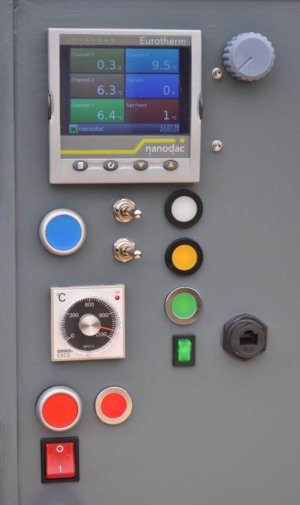
The green rocker switch (beneath the three lamps) controls the power to all the electronic bits in the cabinet so that's the first thing that gets turned on when starting. The red push button is, as described before, the reset for the no-volt release; the red lamp next to it shows when the contactor is closed. The big red rocker switch beneath it goes between the contactor and the heater output so acts as a manual means of disconnecting heater power if required. The rest of the controls (blue push button, two toggle switches, white, yellow & green lamps and the dial in the top-right) are all connected to the Nanodac controller.
The program I've got in the Nanodac at the moment is still a bit of a work-in-progress but so far the things I've got working are:
- The potentiometer (blue dial in the top-right of the photo above) adjusts the set-point (target temperature) with a range of 0°C up to about 1200°C. I won't ever take it right up to that limit as that's getting a bit close to the maximum rating of the chamber components (1260°C).
- The top one of the two toggle switches selects whether to use the potentiometer-configured set-point (switch to the right) or use a hard-coded set-point (currently 810°C) if the switch is to the left.
- The green light comes on when the temperature is within 5°C of the set-point.
- The bottom toggle switch currently just turns the yellow light on and off! I'll come up with something more useful for that in due course.
- The blue push button does nothing at all at the moment and I haven't had any ideas of what it might be useful for yet!
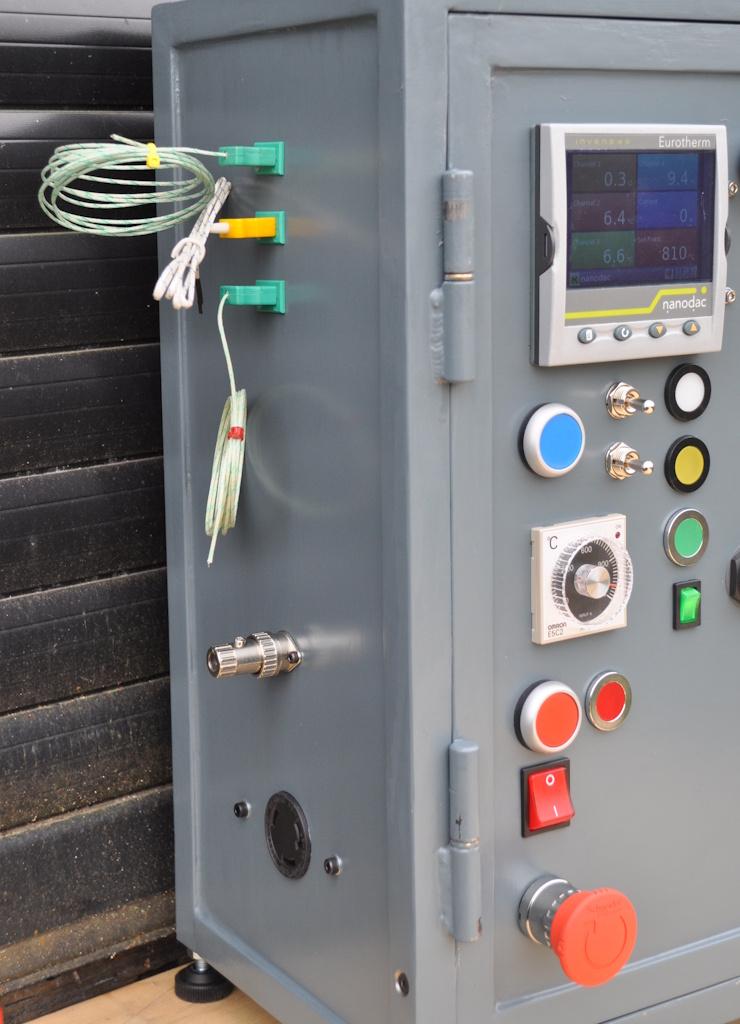
While I've been testing the electronics, I've had a few temporary connections in the side:
The thermocouples are all K-type, but (as you can probably guess) not rated to the temperatures the chamber will get up to. The middle one has a yellow plug rather than the proper green, but it's still K-type. Americans like to do things differently so they use a different colour scheme and the manufacturer of that thermocouple obviously decided to follow the American convention.
You can also see that there's a plug in the socket for the door interlock. That plug has a shorting link to allow me to pretend that the chamber is present and the door is shut. That's just for testing while I fiddle around with the controller configuration and finish building the chamber.
That's it for now. I have done a bit on the door as well, but I'll write that up when I've made a bit more progress and have something interesting to show.
Overall, I'm really, really pleased with how the control cabinet has come out. The paint job looks reasonably good (although there are a couple of bits on the hinges that need touching up following the big wire-up) and the wiring is a lot neater than I expected it to be. I'm sure it would have been far more sensible (and quick) to buy a box and fit the various switch-gear, but there's something quite satisfying about having made this box from scratch.
Page 24 of 35
This website is free and ad-free, but costs me money to run. If you'd like to support this site, please consider making a small donation or sending me a message to let me know what you liked or found useful.

 Return to main project page