Heat Treatment Oven Build Process
Page 3 of 35
Posted 6th May 2024
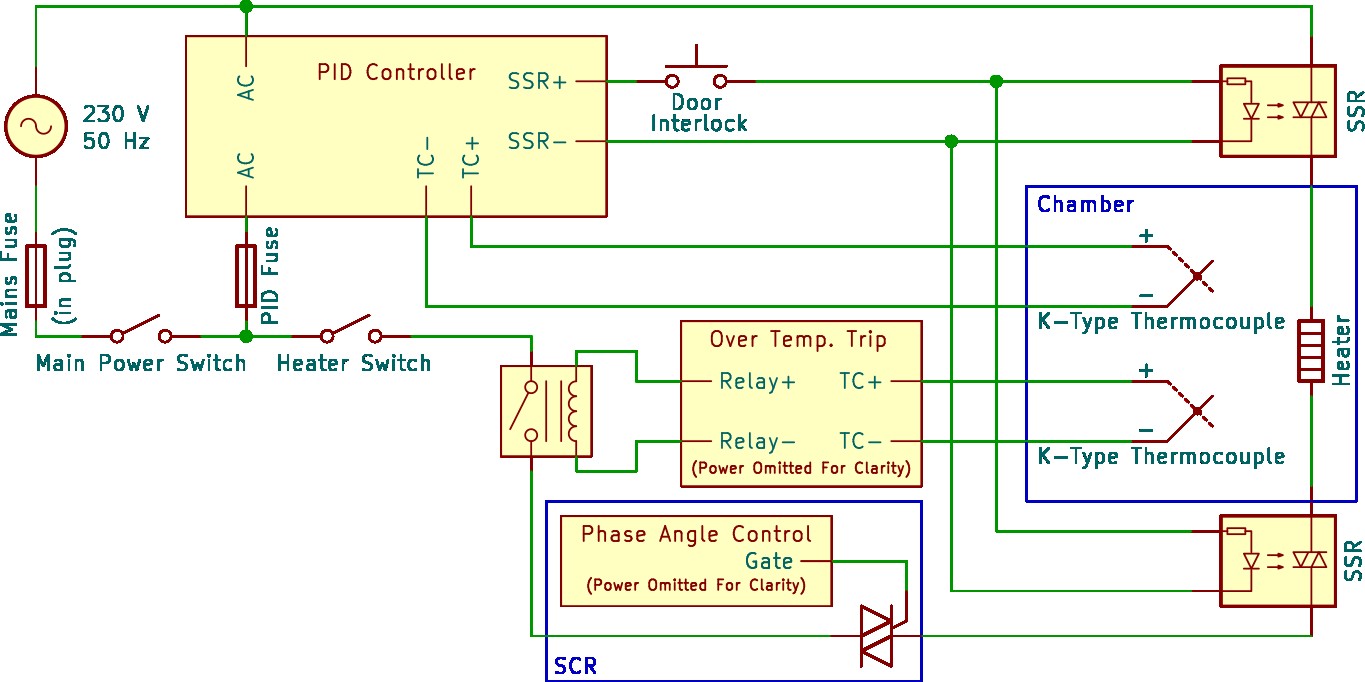
Following some extremely helpful feedback from various people on the MIG welding forum, I've updated the circuit diagram. The main changes are:
- The addition of a second thermocouple, driving a temperature monitor (exactly what form this takes is still to be determined). The temperature monitor is there to cut the power to the heating element in the event of the temperature getting too high (i.e. if the SSRs fail). I've shown this as driving an electromechanical relay as it won't need to switch rapidly and is more likely to fail open-circuit, but it could also take the form of an SSR.
- The addition of a silicon-controlled rectifier (SCR), which could be used to reduce the power into the heating element if desired. I'm not sure whether I'll fit this straight away, but it's good to plan for its possible inclusion at a later date.
- I've changed the schematic symbol for the SSRs to make it clearer that there are two wires from the PID controller.
For now, I've left the second SSR in the circuit. In theory, the over-temperature relay makes the second SSR redundant (and reduces the risk of latent failures where one SSR has failed short and there's no way to tell, meaning I keep using the oven until the second one fails). However, it seems sensible to plan for it even if I don't eventually fit it.
The heating element will be made from "Kanthal A1" resistance heating wire, which is rated for use at temperatures up to 1400°C. I am currently planning on using 1.4 mm wire. Most oven builds I've seen use 1.2 mm or 1.3 mm wire. I couldn't find a source for 1.3 mm wire so the options were 1.2 mm or 1.4 mm. Thicker wire should mean better longevity (i.e. longer before I'll have to take the wire out and replace it). The disadvantages are that it'll take a bit more effort to wind it into a coil and that it's a bit more expensive. The resistance of the 1.4 mm wire is slightly lower than that of 1.2 mm wire (0.92 Ω/m vs 1.28 Ω/m), so this will need to be taken into account: with the 1.4 mm wire I need slightly more wire to get the same overall element resistance (which further adds to the cost over and above the fact that the thicker wire is more expensive).
The overall resistance of the wire is chosen based on the target oven power or current. I'd like the oven to run off a standard 13 A wall plug, although I have a 32 A single-phase socket in the garage, so it wouldn't be the end of the world if I had to go for higher currents. If I aim for 10 A (which I believe is a sensible maximum safe continuous current for most standard UK sockets) then that means I want 25.3 Ω total resistance (the mains RMS voltage in the UK is 230 V ±10%, so the maximum RMS voltage is 253 V and Ohm's Law gives the resistance). That would be 27.5 metres of 1.4 mm wire (or 19.8 metres of 1.2 mm wire). The wire would be formed into a coil, reducing the physical length of the element while increasing its diameter. It's worth noting that this calculation only includes the current in the heating element and the 10 A target may have to be reduced a bit depending on the current consumption of the various bits of control gear (assuming they are all powered from the same plug as the element).
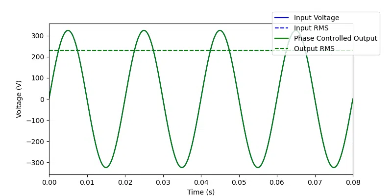
The updated circuit diagram above includes a phase-angle controlled silicon-controlled rectifier (SCR), which could be used to reduce the RMS voltage and thereby reduce the current for a given length of resistance wire. However, if possible, I'd like to design the system to be able to cope with full mains voltage across the element, even if I then decide to lower that voltage for actual use.
The power output of the oven at 10 A and nominal voltage (230 V) would be 2300 W. If I design for a 150 mm × 150 mm × 200 mm internal space, then that's 4.5 litres and hence the power would be 511 watts/litre. By comparison, the commercial Evenheat LB 18 and Paragon DB 18" heat treatment ovens work out as 188 watts/litre and 222 watts/litre respectively, so that suggests I could lower the current without having to worry too much about having enough power. Lowering the current means increasing the length of the wire (to increase the resistance) or reducing the RMS input voltage with the SCR. Those calculations are likely to change after I've revisited the brick layout (which may change the volume of the cavity).
Page 3 of 35
This website is free and ad-free, but costs me money to run. If you'd like to support this site, please consider making a small donation or sending me a message to let me know what you liked or found useful.

 Return to main project page

