Travel Tool Chest & Workbench Build Process
Page 100 of 144
Posted 22nd October 2023
Today was a fairly long day in the metal-mangling end of the workshop. It all started with taking the milling machine apart to try to get to the bottom of a temperamental spindle-speed display. I'd assumed it was a result of a vibrating connector on one of the looms that snake their way around the mill. I'd already tried hot glue on the most accessible of them, but I was still having problems so I decided to move the milling machine out and investigate the other end. After moving it and dismantling it, the other end looked fine, so I realised it must be a bad connection on one of the PCBs. Best guess was the display PCB, so I took it out, wicked away all the (lead-free) solder and re-soldered all the joints with leaded solder. After putting it back together, all was sorted and it seems to be working consistently now, even when the mill is a bit vibratey.
With that done, I could get on with the task I was planning to use the mill for.
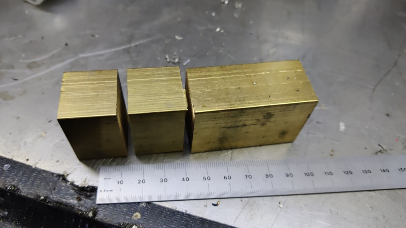
It all started with a lump of 25 × 35 mm brass, which I chopped up into bits:
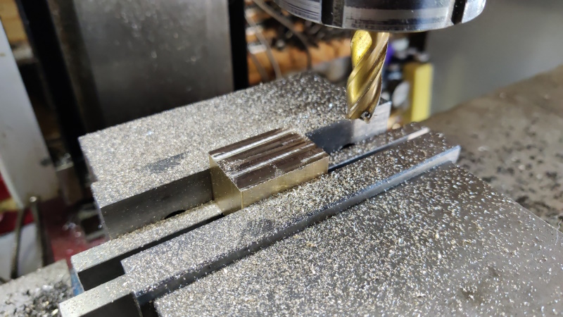
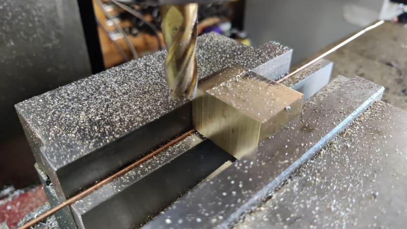
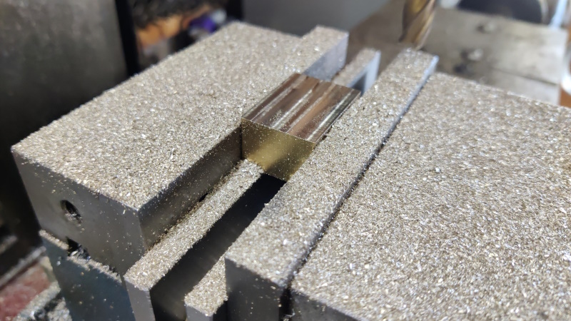
I then went through the three-step process of squaring up the sawn ends with the other four faces and bringing the thickness down to 18 mm:
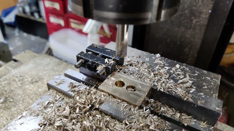
Two 8 mm diameter holes were drilled, 10 mm apart, down to a point depth of about 15 mm:
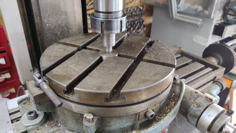
The next job needed my rotary table, which doesn't get used much, but it's very useful on occasion. The first job was to align the centre of the rotary table with the spindle and then zero the axes so I could always refer back to that centre:
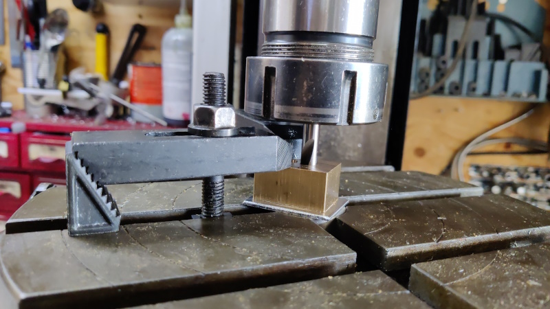
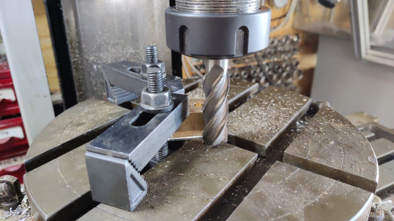
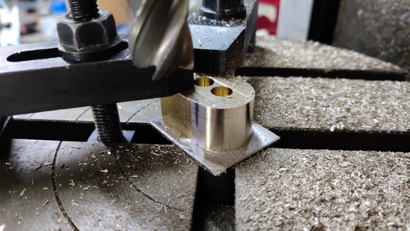
The part was then mounted on top of a little scrap of aluminium sheet, using the 8 mm spotting drill in the chuck to ensure that one of the holes was centred on the centre of the rotary table:
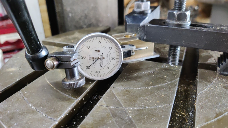
With that done (and the clamps as far out of the way as I could manage), I rotated the rotary table and tweaked it back and forth until a DTI running along the side of the part showed it to be aligned with the X-axis of the machine:
With it aligned nicely, I could zero the rotary table dials and put some pen marks on the table to show me where I needed to stop (it's very easy to overrun!). Then it was just a case of sticking a gert long 18 mm end mill in the chuck and gradually reducing the end of the piece to have a 12 mm radius / 24 mm diameter.
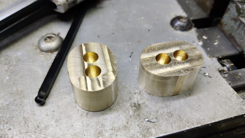
With one end done, I then removed the part, got the spindle back over the centre of the rotary table, fitted the part the other way round, clamped it down, used the DTI to zero the rotary table again, then milled the other end 24 mm diameter.
... and again with the second part, one end then the other.
The parts started off as 25 mm wide but the ends are 24 mm diameter, so there's now a lump in the middle. In theory, I could have milled the sides while on the rotary table, but the clamps would have got in the way and it would have been a pain in the backside, so I decided to use a different approach.
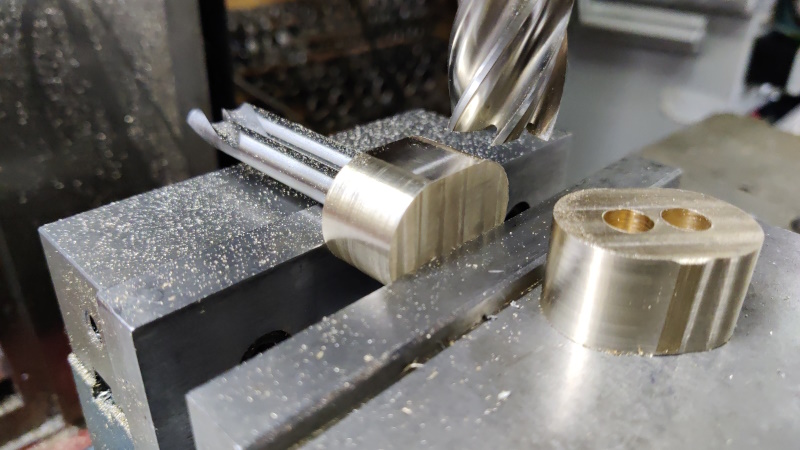
I shoved a couple of 8 mm spotting drills in the holes and used the spotting drills to ensure that the part was aligned with the top of the vice jaw (which I've already checked is level with the lathe axis). It was then quite simple to get rid of the excess 0.5 mm.
Turn it over, rinse & repeat; swap for the other part, rinse and repeat. You get the idea.
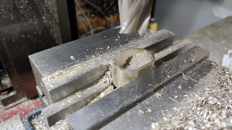
With the outside profile complete, I could hollow out the inside. First with a 16 mm slot drill down to 15.8 mm depth, then with a 19.6 mm end mill (I bought it second hand: I think it's a 20 mm end mill that had been sharpened a few times, hence the reduction in diameter) down to 16 mm depth.
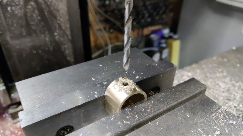
The last milling job on these pieces was to cross-drill a 4.1 mm hole all the way through, 10 mm from the front face of the part:
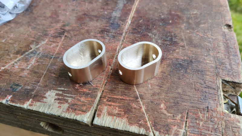
A quick rub back-and-forth on some 180 grit wet-and-dry paper and the back pieces are complete:
All of the above (apart from the cross-drilling) could probably have been done in a single setting on a CNC mill and taken a few minutes, but it took me most of the day!
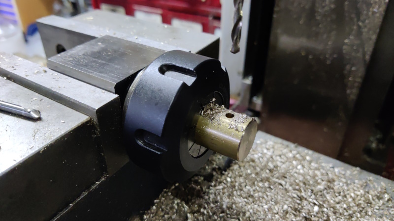
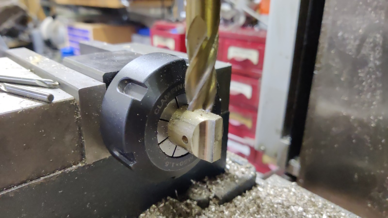
I had a handy little bar of 20 mm round brass, so I faced both ends in the lathe and then put it in a collet block on the milling machine. After finding the location of the end and the centre across the width, I cross-drilled a 4 mm hole all the way through:
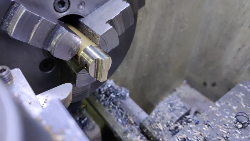
I then turned the collet block through 90° and used a 12 mm end mill to cut a couple of indenty things:
I then turned the bar round in the collet block and did the same two operations on the other end of the bar.
The bar was then chucked in the lathe and the outside diameter turned to fit smoothly into the back pieces I hollowed out earlier:
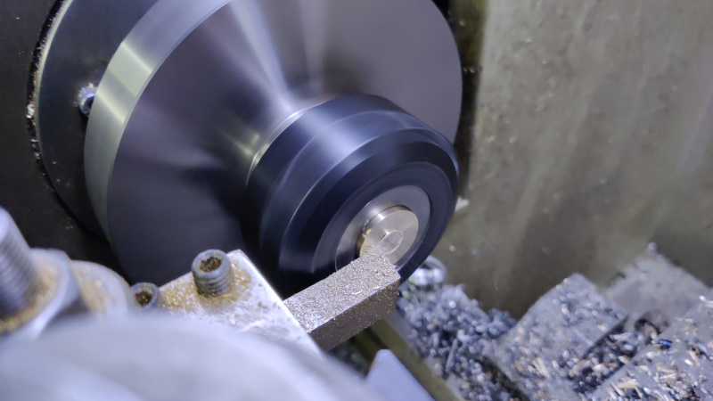
After sawing the parts off the parent bar, each then went back to the lathe to have the sawn end faced to length:
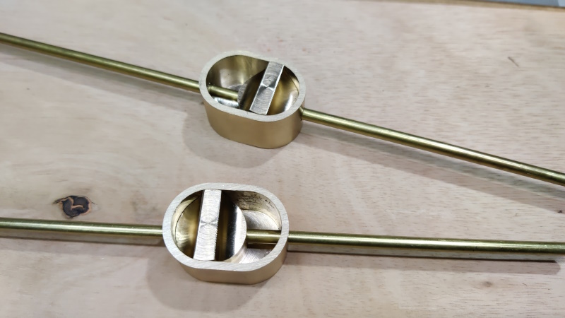
After grabbing a couple of bits of 4 mm brass bar out of the drawer, I could give them a try:
The plan is to sink the back pieces into the underside of the shooting board and drill a hole into each end of the shooting board. The bar can then be passed through the shooting board end hole and into the back piece. A bit of glue will hold it into the knob thing and then the knob can be moved left-to-right to push the 4 mm bars out of the ends of the shooting board and hence hold it in place in the front of the chest and stop the drawers coming out.
That all sounds very simple when I say it like that, but there are a couple of fairly major challenges to overcome:
- How to drill an 18 mm deep blind flat-bottomed hole in a 20 mm thick shooting board. The easy way to do this would be a template and a power router, but I've promised myself I won't do any powered woodwork (apart from bandsaw resawing) on this project, so that's out. A 24 mm Forstner bit on each end will definitely help get it started, but the point of the Forstner bit protrudes quite a long a way, so I don't think I'll be able to go all the way down (at least not without the Forstner bit point coming through the other side). The best idea I've had for this so far is the 24 mm Forstner bit as far as possible on each end of the pocket, then chisels and small router plane to finish it off. If it ends up a bit undercut at the bottom of the hole, it won't really matter.
- How to make sure the holes I drill in the ends of the shooting board come out in the right place to mate with the slidey locking things. To some degree I can make that easier on myself by drilling the holes oversize, but there's only so much oversize I can go.
Page 100 of 144
This website is free and ad-free, but costs me money to run. If you'd like to support this site, please consider making a small donation or sending me a message to let me know what you liked or found useful.

 Return to main project page