Woodturning Lathe Build Process
Page 18 of 57
Posted 1st March 2024
I've been working on the tool rest slide mechanism gradually in amongst other jobs, but I thought I'd wait until it was mostly complete before posting the photos and build process as I figured it would make more sense as a fait accompli.
The first piece to describe is the part I'm calling the clamp block. This sits inside the "t-section" of the tool rest slide and can move along to any position along the length. When the tool rest slide is clamped, this piece is the one that presses down on the tool rest slide and holds it in place.
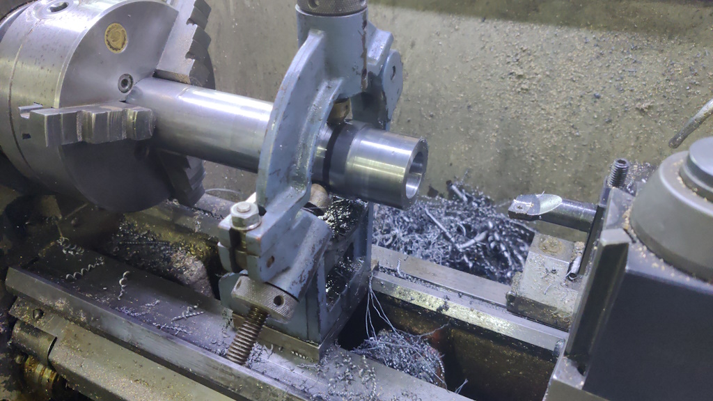
I started with a length of 50 mm diameter EN1A. It's too large to go through the chuck, so I used a fixed steady to support the outer end while I turned the outer diameter down to a bit less than 46 mm and bored a (slightly under) 30 mm hole through the middle:
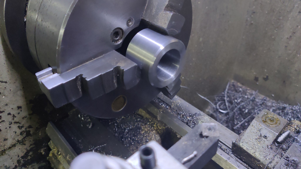
After cutting the end off with the bandsaw, I put it back in the chuck the other way round and faced the end. I also added a heavy chamfer to this end so that it was obvious which end had been faced in the same setting as the central bore. The chamfered end will be the top and it doesn't matter if that isn't perfectly square to the bore.
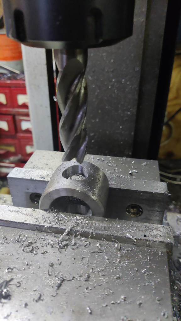
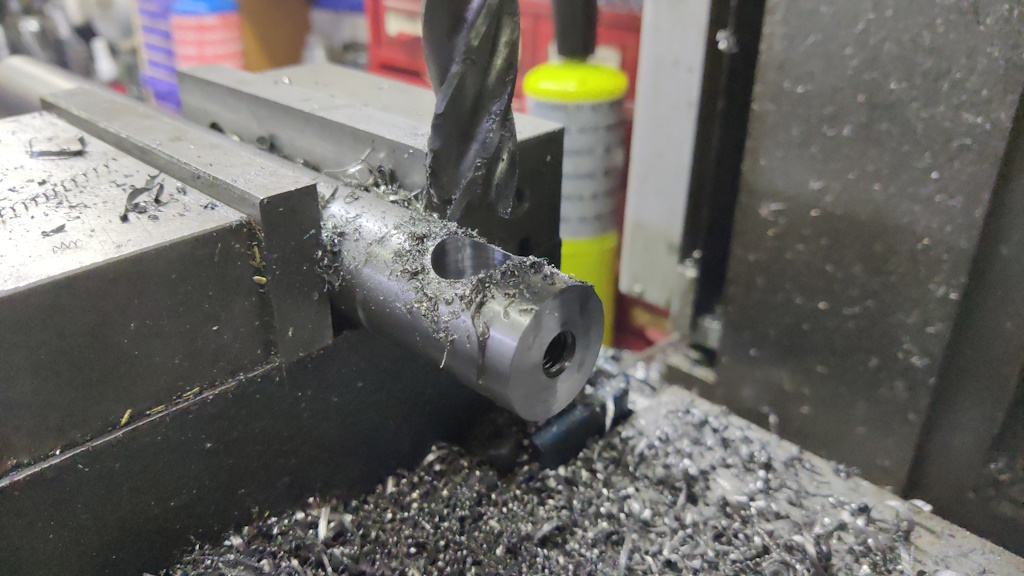
The part then got clamped in the mill vice and I drilled an 18 mm cross hole, 16 mm from the base. I did this with drill bits up to 13 mm and then 14 mm, 16 mm and 18 mm end mills to bring the hole to the final size:
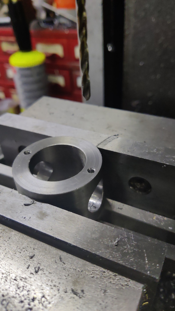
It was then placed in the vice in the other orientation with the base facing upwards. I aligned it (very roughly) by lying a bit of 12 mm (the first piece that came to hand!) bar through the 18 mm cross holes and rotating the clamp block until it looked about right. Again, it would have been better to use a V-block for better clamping, but I didn't have one that was big enough and I'm only drilling so I didn't think it was important. With it clamped in the vice, I spot drilled and drilled two 3.3 mm holes:
Those holes then got tapped M4, but I did that by hand in the bench vice rather than trying to machine tap while the part was held rather weakly in the machine vice.
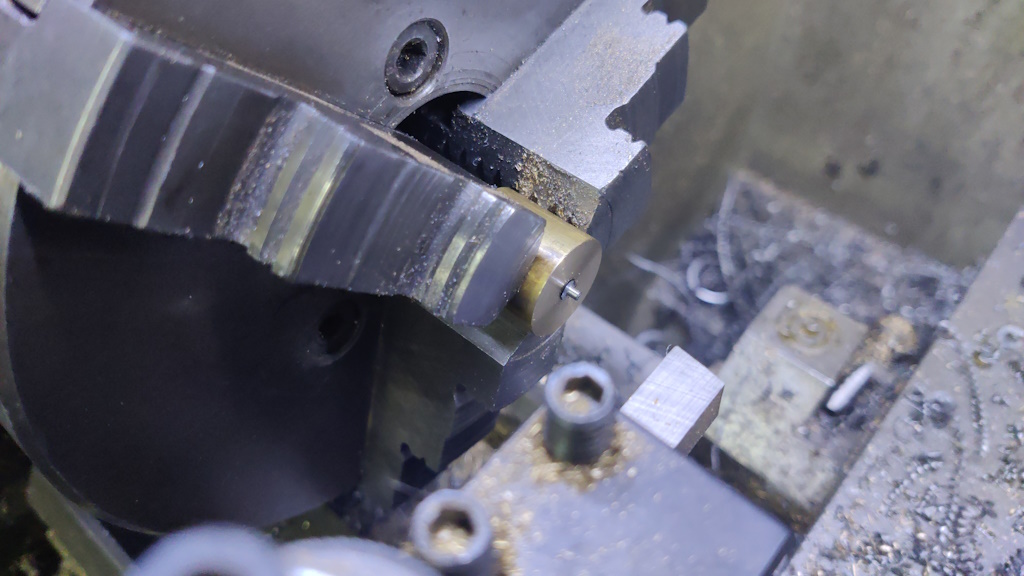
I then needed some modified M4×8 cap screws for those holes. The screws need to have a short 2 mm diameter section on the very end. To hold them for modifying, I drilled and tapped an M4 hole in an offcut of brass and then used an end mill to bore through most of the hole, leaving a flat bottom and about 5 mm of thread remaining. That could then be mounted in the chuck and I could tweak the end of the cap screw. I had to do this with the tool upside down and the lathe running backwards; otherwise the cutting force would have just unscrewed the cap screw from the brass bit.
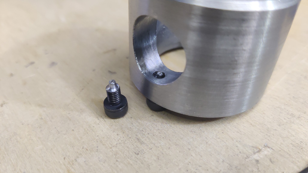
This photo shows one of the modified screws on the bench and another fitted into the threaded hole in the clamp block:
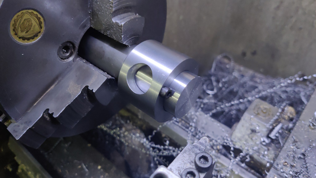
The "clamp nut" is made from 30 mm EN1A. I'm calling it a clamp nut, but it's really a screw that happens to be made in two parts: the "nut" with an internal thread and a bit of threaded rod glued into that thread. I started by skimming the outside diameter until it was a nice smooth sliding fit in the clamp block:
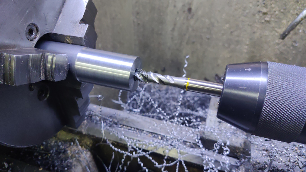
I then drilled and tapped a blind M10 hole, about 15 mm deep:
The bar then got clamped in the mill vice and an 18 mm hole cross-drilled, in the same way as was done for the clamp block:
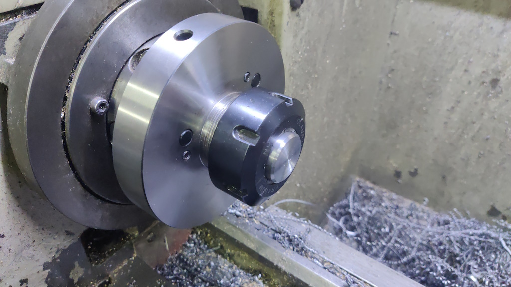
Finally (for this part), the clamp nut was sawn off the bar and held in a collet chuck for facing/chamfering the top end.
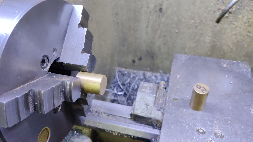
The next job was to make a couple of end caps / bushes. These started life as a couple of offcuts of 20 mm brass bar:
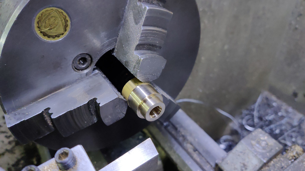
The first job was to shape the end, reducing the diameter to 15 mm for 6 mm length and skimming the outside diameter for a clean look. An 8 mm hole was drilled through and then opened up to 9.2 mm for a couple of millimetres:
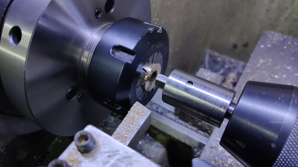
After parting off, it was mounted in a collet (with the other one at the back end of the collet to help ensure that the collet held tightly on this short part) and the end was faced. I used my Hemingway Kits rotary broach to turn the 8 mm hole into an 8 mm deep 8 mm AF hex hole:
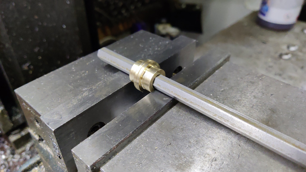
These parts need a cross-hole for a grub screw, so I mounted them together in the mill vice, using a length of 8 mm hex bar to align the internal hex hole with the jaws of the vice:
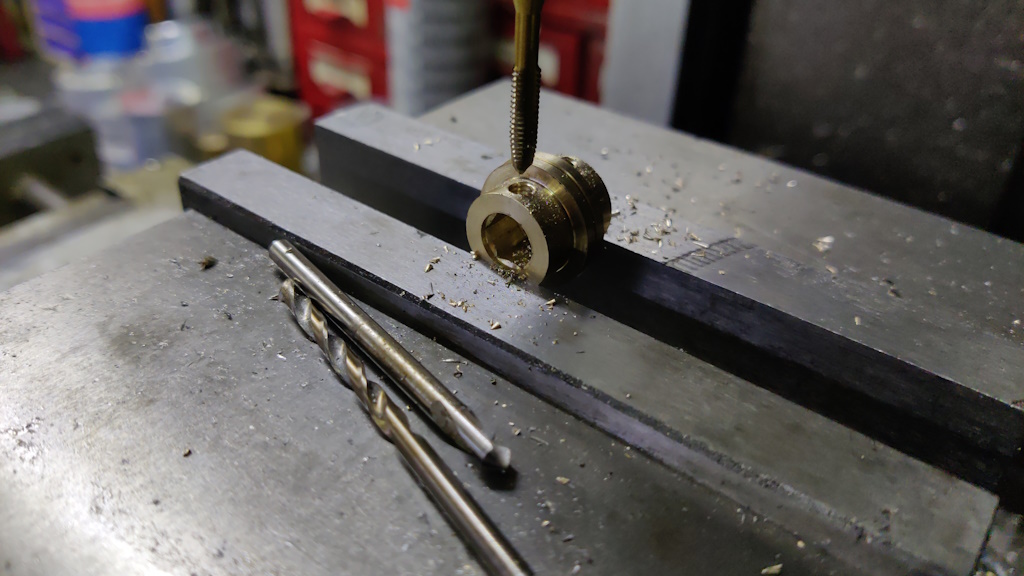
I could then drill and tap an M4 hole in each piece:
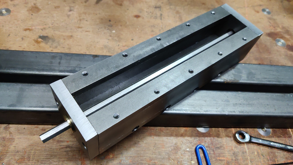
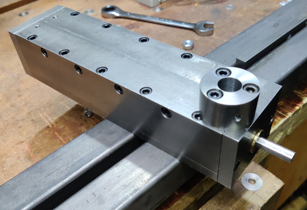
This photo shows how those end caps fit into the end plates of the tool rest slide and support the hex bar that runs along the length. This photo was taken before I drilled the extra holes in the bottom of the tool rest slide that give access for a 2 mm Allen key for tightening/loosening the grub screws that hold the brass bushes/end caps onto the hex bar. The brass bushes rotate freely in the holes in the end plates and hence the hex bar can be rotated freely.
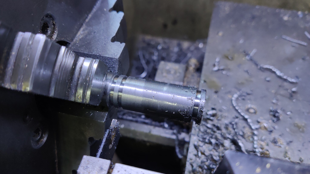
That brings us to the last piece of the puzzle. I started with a bit of 18 mm round bar and, after facing the end square, I used a 2 mm wide parting tool to cut two grooves in the part (and also to mark the length of the bar - that's the groove nearest the chuck):
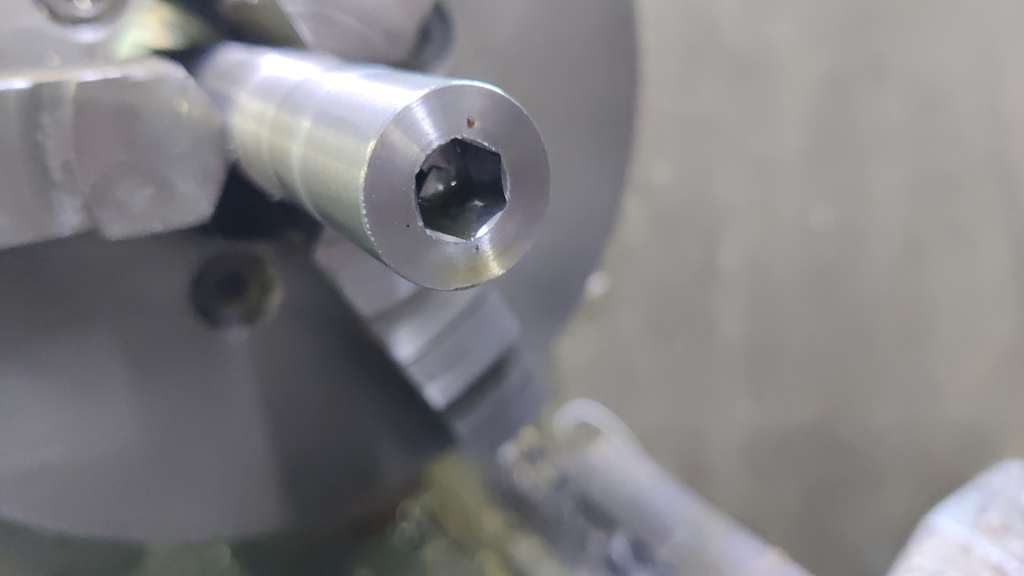
An 8 mm hole was drilled through the part and then the rotary broach was used to turn it into an 8 mm AF hex hole, going as deep as the tool would allow (which is about 8 mm):
The resulting hole:
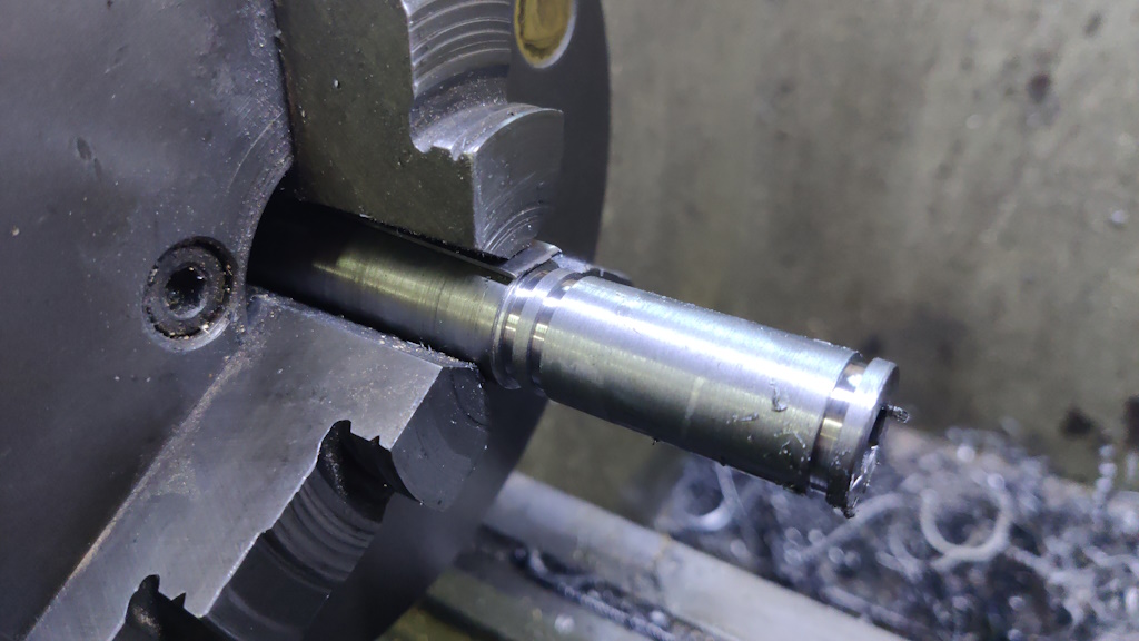
With the hole cut, I could work on the eccentric cam section. I added an 0.8 mm piece of feeler gauge stock to one of the jaws of the chuck:
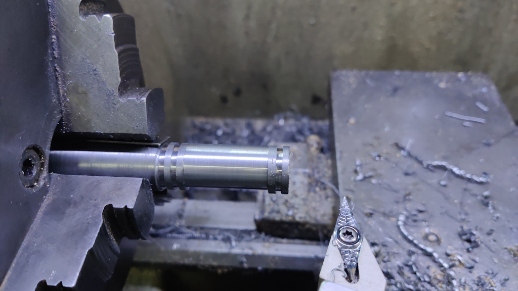
I could then use a pointy tool to cut the central section of the piece. I wasn't aiming for a specific diameter here, I just kept taking passes until the tool was cutting continuously:
The final operation on this part (for which I didn't take any photos) was to cut it off the bar, mount it the other way round in the collet chuck and face the back end. I then used a 9.2 mm drill bit to drill most of the way through the part, leaving the final 8 mm-ish. The reason for that final drilling operation is that I want an 8 mm hex bar to pass all the way through the cam. My rotary broach will only cut about 8 mm deep, so the rest of the length has to be drilled wider to allow the across-corner dimension of the hex bar to go through. Theoretically this dimension is 8×2÷√3 = 9.238 mm, but I measured the size of my hex bar and it was slightly under 9.2 mm.
With the final part made, I could assemble the tool rest slide:
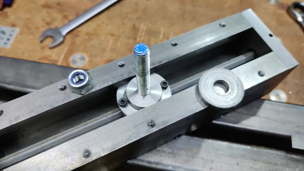
This shows the underside of the assembled tool rest slide:
The two modified M4 cap screws engage with the grooves in the cam and stop it from sliding out of the clamp block. Rotating the cam section lifts or lowers (under gravity) the clamp nut (and hence the M10 threaded rod). The big washer and the nyloc nut bear against the bottom of the bed.
As the threaded rod is round, the tool rest slide can be rotated to any angle. As the clamp block / clamp nut / cam assembly can slide freely along the hex bar, the tool rest slide can be moved back and forth across the bed (as well as along the bed). Rotating the hex bar (via a yet-to-be-made handle) by about 90° is enough to release/lock the tool rest slide to the bed.
This very short video shows the action of the lock (using an 8 mm spanner as a temporary lock handle and with the "bed" bodged as two bits of box section clamped round some 12 mm plate and then clamped to the bench).
I spent quite a lot of time thinking about how to make the tool rest slide (not least making a hex hole for a 45 mm long cam to slide along a hex bar) and I'm really pleased with how it's working. The action of sliding is a little bit rough, but that's just because of the rough finish on the box section. It should be very quick and easy to adjust the position of the tool rest with this mechanism.
Page 18 of 57
This website is free and ad-free, but costs me money to run. If you'd like to support this site, please consider making a small donation or sending me a message to let me know what you liked or found useful.

 Return to main project page