Woodturning Lathe Build Process
Page 20 of 65
Posted 2nd March 2024
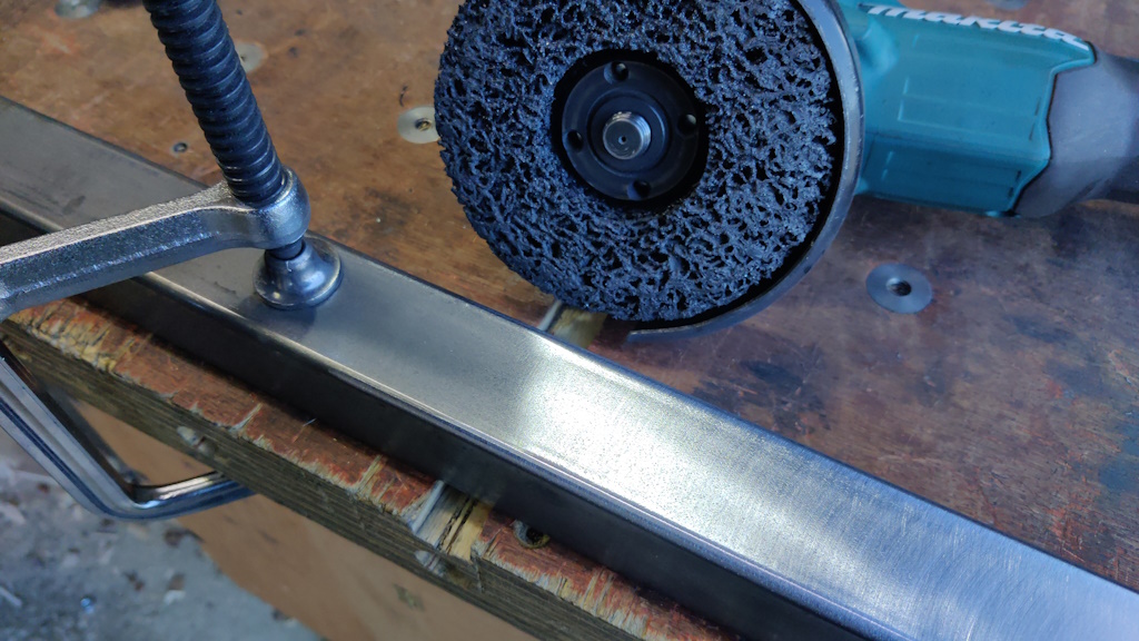
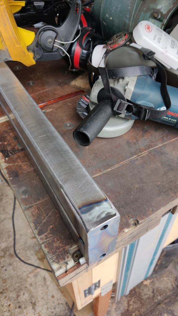
The first job for the lathe bed was to use a non-woven preparation wheel to clean up all the mill scale:
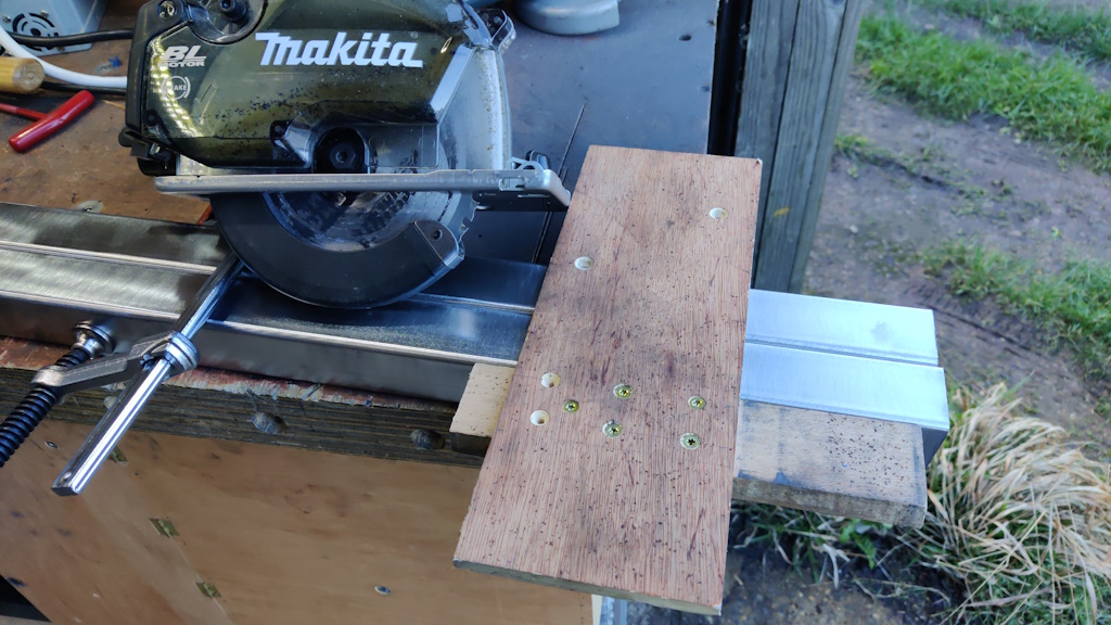
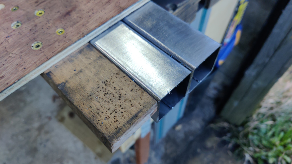
After clamping the two pieces together, my metal-cutting circular saw could then trim the two pieces to the same length, using this plywood guide:
The plywood piece ensures the saw cuts square; the fence was cut to length with the saw itself, so makes it very easy to see where the cut line will be.
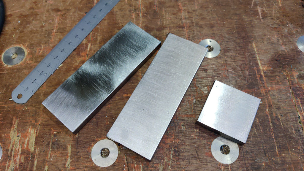
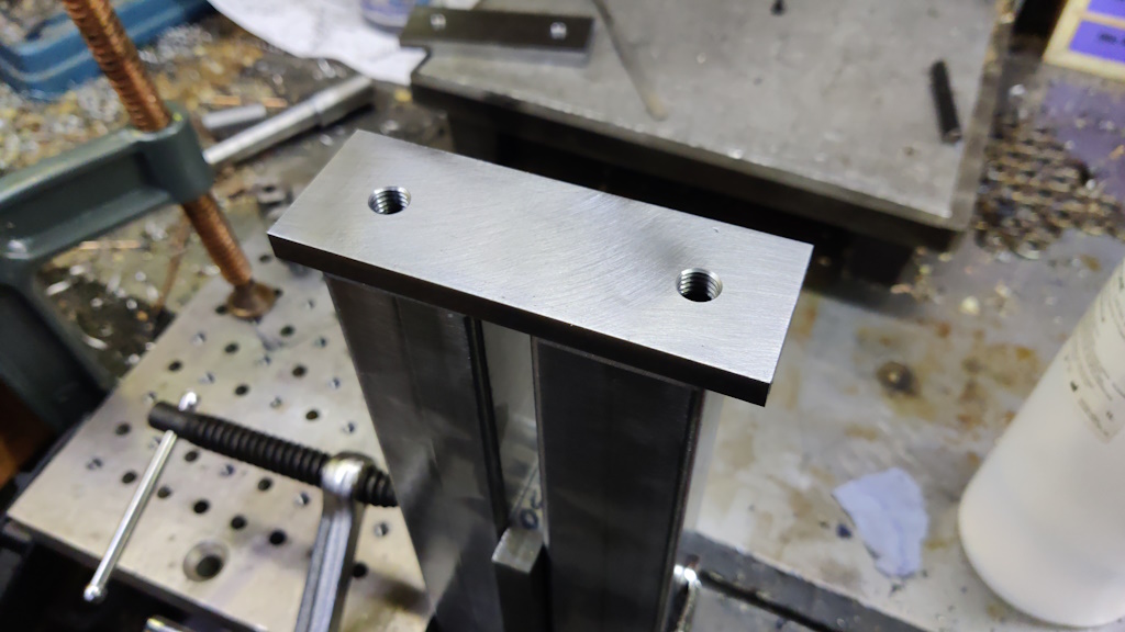
Some end plates, made of 8 mm × 40 mm EN3B were also cleaned up and cut to length in the same manner, along with a piece to use to hold the tailstock bearing in place.
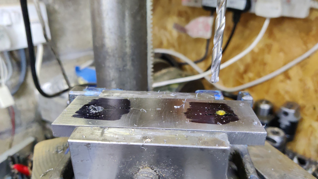
I drilled some holes in the plates. I'm not really sure what they'll be used for, if anything, but I needed at least one hole in each piece to allow air to escape when welding and I figured it would be a lot easier to drill and tap holes before welding the plates onto the ends of the bars.
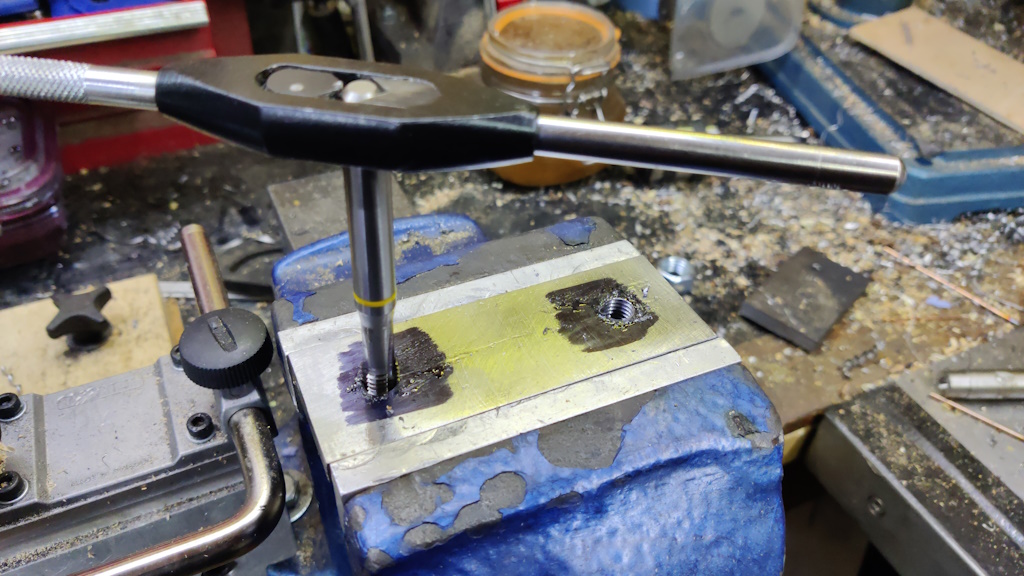
They were tapped M10 by hand in the bench vice.
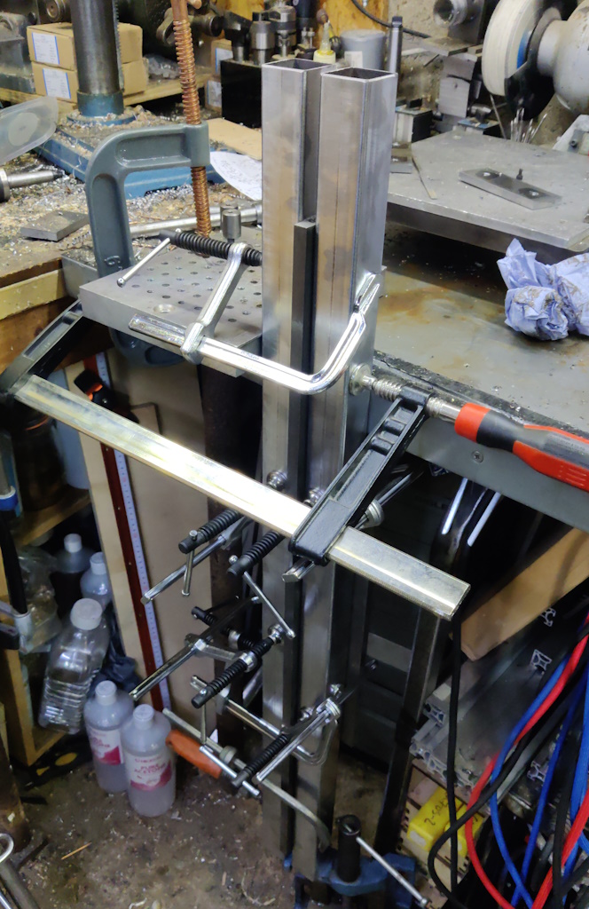
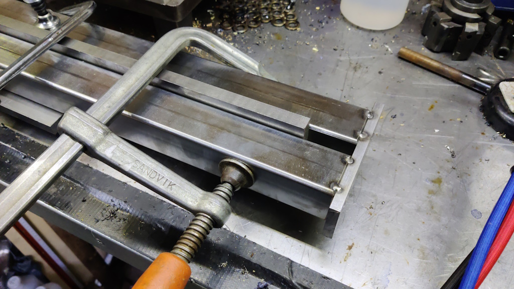
The bed pieces then got clamped down to a bit of 12 mm × 125 mm steel plate (to keep them level) and clamped around some bits of 12 mm × 50 mm flat bar to keep them parallel and the right distance apart:
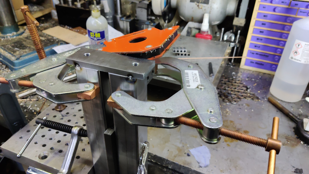
To hold the bed upright, I used a G-clamp to hold a piece of aluminium to the bench and an F-clamp to hold the bed to the piece of aluminium, resting the end of the bed on a vice to raise it up a bit and make it easier to hold for clamping:
I then offered up the end plate and demonstrated that having a PhD in electronic engineering and spending a considerable amount of my career solving complex differential equations doesn't necessarily equate to doing basic addition:
Those plates were supposed to be cut to the same length as the depth of the bed, but somehow I was 20 mm out. Cutting that plate was the last thing I did last night, so I guess that shows that I shouldn't try to engage my brain at the end of the day!
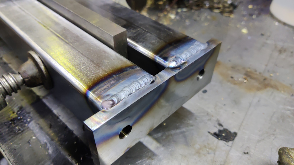
Never mind... I can sort that out later. Another couple of clamps were added to keep the bed top surface flat near the ends and then I tack-welded the end plates in place:
I could move the bed to a more comfortable position for welding:
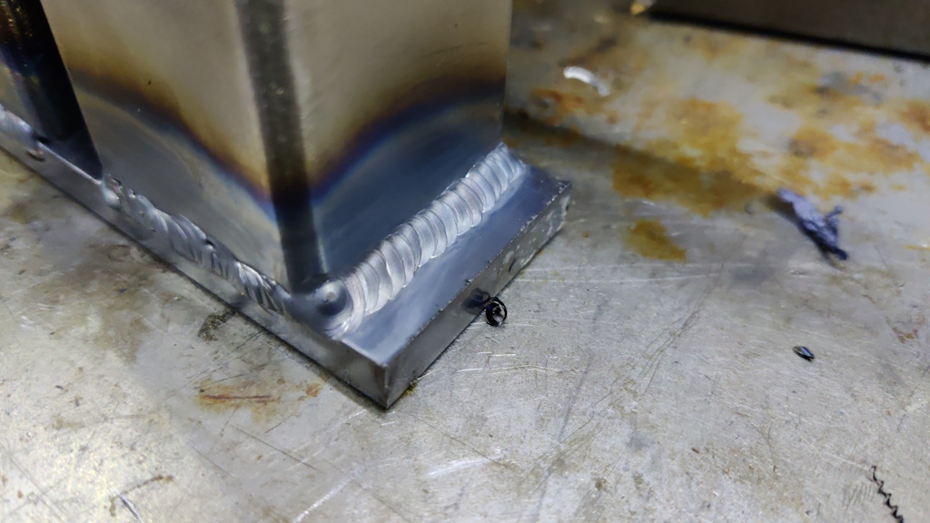
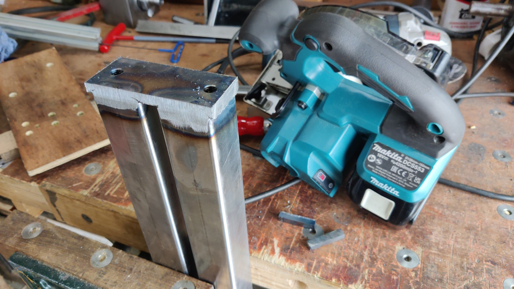
The overhanging end plates meant I had to weld round the sides with the bed standing on end, but that wasn't too much of a problem:
I used the metal-cutting circular saw again to trim off the bit that shouldn't have been there...
... and then cleaned the ends up with a flap disk:
The bed is essentially done now, although I'll probably add some threaded holes in the bottom for attaching feet and/or the motor assembly.
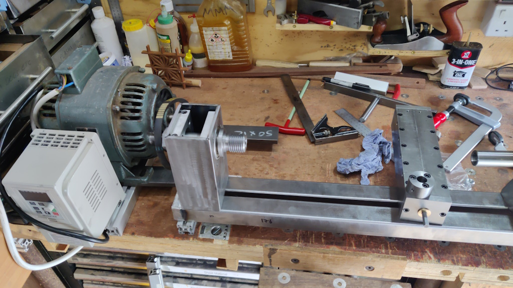
With that done, it was time to play around with different layouts so that I could try to figure out how to mount the motor. One option is to mount the motor with the spindle pointing to the left. This would keep the overall length of the lathe to a minimum, but the motor would have to be a long way back in order to give clearance for the tool rest slide:
The support piece (currently a bit of 3030 t-slot extrusion) for the right-hand side of the motor also limits the left-ward travel of the tool rest slide.
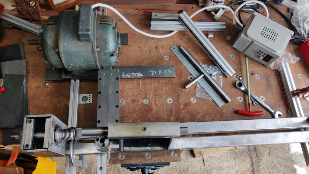
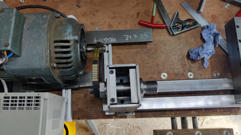
The alternative (and the one I'm currently leaning towards) is to have the motor spindle pointing to the right. That allows the motor to be much, much closer to the spindle (it might even allow me to use the one and only drive belt I already have), but makes the overall length of the lathe much greater.
Other advantages of this layout are that it gives somewhere fairly logical for the inverter to go and it means the tool rest slide can go anywhere along the bed with no interference. Top view:
The main disadvantage of this layout is that it's going to need some thought to figure out how to attach the motor to the bed in a robust enough way to tension the drive belt. I quite like the idea of using the 3030 t-slot extrusion for the motor mount as it gives me a t-slot "for free" and I can use that to slide the motor back and forth to tension / loosen the belt. However, as-is, it would be completely independent of the bed and that might not be great for tensioning.
The simplest option would be to clamp the motor mount assembly (i.e. t-slot extrusion) to the bench and independently clamp the lathe bed to the bench. That would probably work fine, but I suspect it would be better (and easier to set up) if the two are attached in some way.
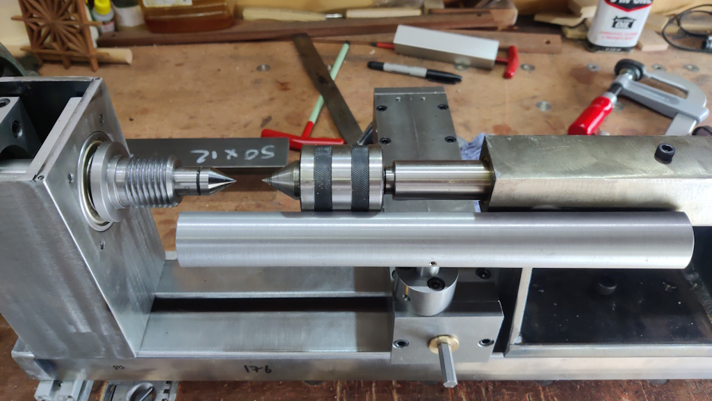
While I had the bed clamped to the bench, I also shoved a live centre in the tail stock and a (rather inappropriate) metal-work dead centre in the headstock and had a little play with the tool rest and how limiting the length of it would be:
Page 20 of 65
This website is free and ad-free, but costs me money to run. If you'd like to support this site, please consider making a small donation or sending me a message to let me know what you liked or found useful.

 Return to main project page