Woodturning Lathe Build Process
Page 6 of 43
Posted 11th February 2024
Today I've been working on two different jobs in parallel. I started work on the tailstock body as the first jobs on the headstock body were going to be noisy and I was out in the workshop a bit too early to feel comfortable waking the neighbours up. Once it had got to 11am, I started on the headstock body and focused on that, although there were a few times when the headstock body needed to cool down and I switched back to the tailstock body.
I'll try to write this up as if I did them one at a time though as I think it'll be easier to follow.
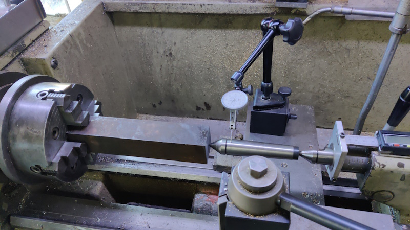
The first job on the tailstock body was to mark a centre point on each end and then mount it in the four jaw chuck on the lathe. A dial test indicator was used to get that centre point bang on centre.
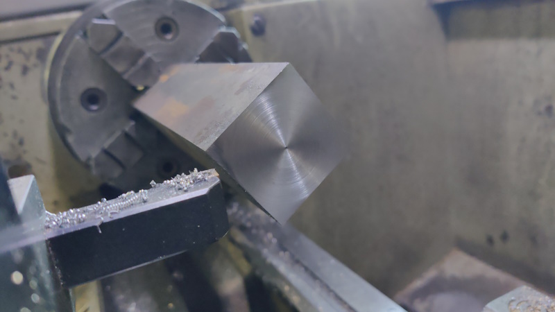
I then faced the end (taking very light cuts and with the lathe running slowly as that bar is sticking out a very long way from the chuck!)
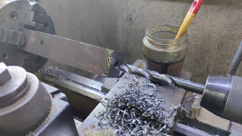
Once it was faced, I spot drilled a centre mark and then worked my way through my drill bits. I started at 10 mm, drilling as deep as I could:
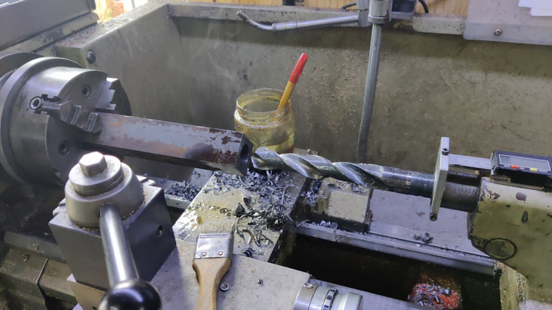
I then went up through my big drill bits, which I've got in steps of 3 mm, drilling as deep as possible with each of 13 mm, 16 mm, 19 mm, 22 mm and finally 25 mm:
I'd recently sharpened all of those drill bits except the 22 mm one and it was quite noticeable how much harder it was to drill with the 22 mm one, so I stopped and sharpened it before continuing! The first section of drilling was quite easy going (up to the depth of the last drill bit), but each drill bit was a bit longer than the last, so the last bit was very slow going as the drill bit was removing the full diameter.
Unfortunately, even my massive 25 mm drill bit wasn't long enough to go all the way through, so I'll have to drill in from the other side. I don't think it'll be the end of the world if the two holes aren't spot-on concentric as only the first half-ish of the hole is critical.
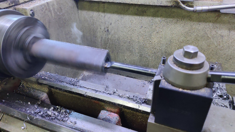
Once I'd run out of drill bits, I used a big boring bar to bore as deep as I could (a bit over half way). I enlarged the hole gradually until it was a bit under 30 mm with a CCMT tip:
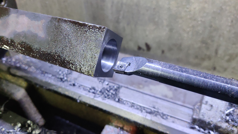
Then switched to a polished CCGT tip and took a single light pass. The diameter isn't that critical as I'll be sizing the component that goes in that hole to fit the hole, but it's about 30 mm.
That's all I've done so far on the tailstock body. Next job will be to turn it round and drill / bore some features from the other end.
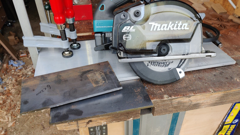
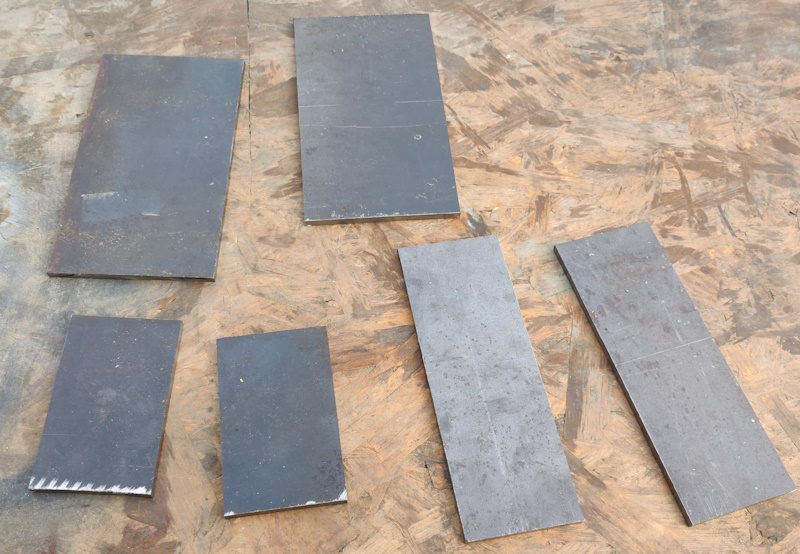
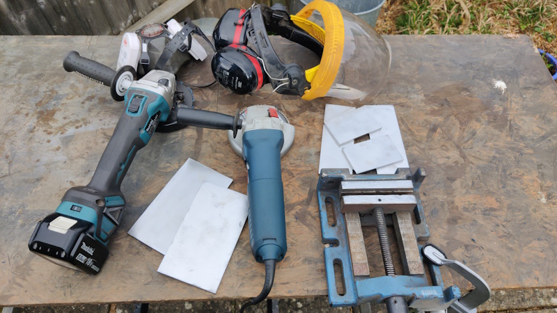
The headstock is going to be made from 6 mm steel plate (mainly because I've got quite a lot of it). I'd been pondering on how to cut the plate up as it was too big for my bandsaw. I've got a cheap ebay plasma cutter, which would cut through it like a knife through butter, but it would leave a rather shabby edge (although that's probably partly down to my lack of skill rather than an inherent flaw of the tool!). I've also got a Makita cordless metal-cutting circular saw, which I've never used on anything thicker than about 3 mm. The manual says it can cut thicker, so I thought I'd give it go.
Wow. It went through that 6 mm plate at the sort of speed I'd expect a "normal" circular saw to cut through hardwood. It also left a fairly clean edge at the end and most of the swarf got caught in the hopper thing. I'm very, very impressed.
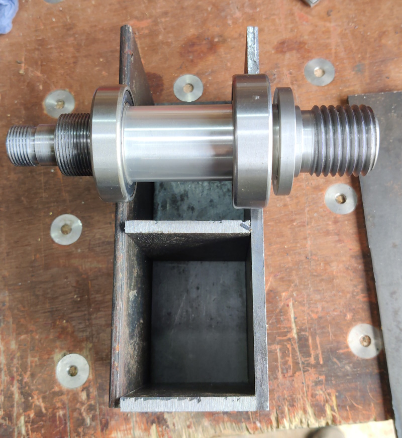
With the plates cut roughly to size, I could have a look at the general arrangement:
Obviously the spindle will eventually go through the middle of the headstock, but I thought it was instructive to lie it on top to show roughly where it will end up. Incidentally, I've settled on a centre height of about 125 mm (so the maximum diameter workpiece that could be "swung" would be 250 mm). I can't see me ever needing to turn anything that big, but at least it'll give plenty of room for me to make the tool support as big as I like.
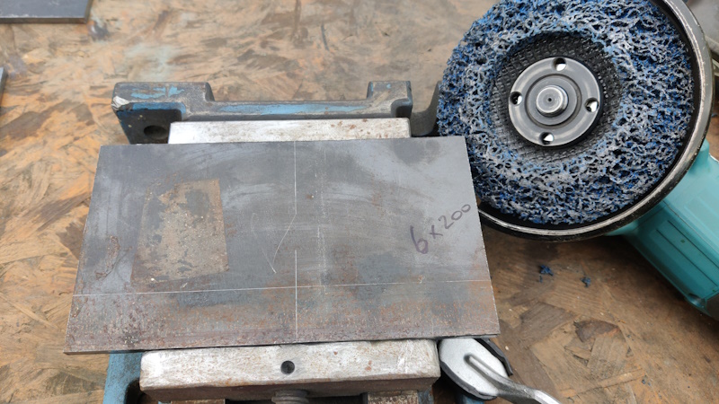
With all the bits cut to final size, I had a lot of mill scale to remove:
I used one of these "non-woven preparation wheels" to remove the scale:
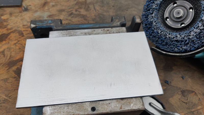
They work really well, removing the scale easily without taking away much steel so they leave a good finish and a flat surface:
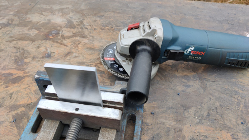
The only disadvantage of them is that they only really work with a relatively slow running speed, so they need a variable speed grinder. That meant using the cordless one, which is quite heavy and unwieldy and chews through batteries (although it is definitely very convenient).
With the faces all cleaned up, I gave the ends a touch up with a flap disc, this time using the mains grinder:
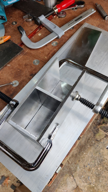
With that done, the bits are nearly ready to be welded together:
A quick test fit to confirm everything looks okay:
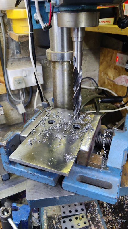
Before starting welding, I thought I'd drill a few strategically located holes. Two 10 mm ones on what will be the rear face, two 16 mm ones on what will be the front face and a couple of M10 tapped holes in the inner shelf. The tapped holes will probably never get used, but if I decide I need a bit more weight, I can fill the bottom pocket with sand through the tapped holes (after plugging the holes in the front and rear faces) and then put some screws in the holes to stop the sand coming back out. As the location of the holes wasn't especially critical, I drilled them with the pillar drill (as it's a lot quicker than setting up the milling machine):
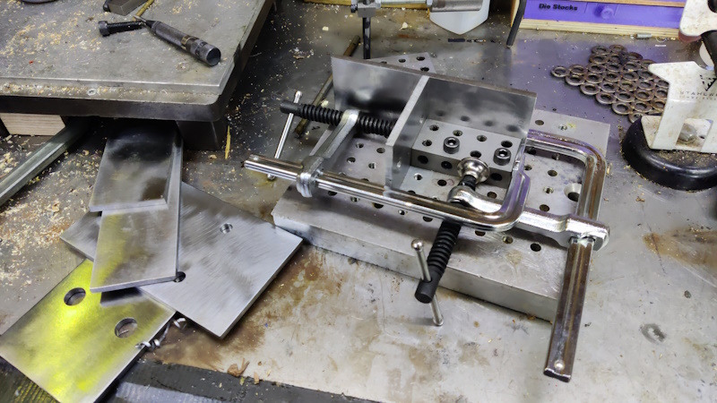
I used a simple jig that I made a few years ago (basically just some aluminium with lots of drilled holes and lots of tapped holes) to help hold things square:
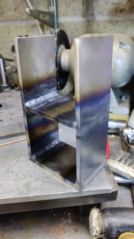
With that done, there was nothing left but to get on with the "hot-melt gluing", first the inner frame:
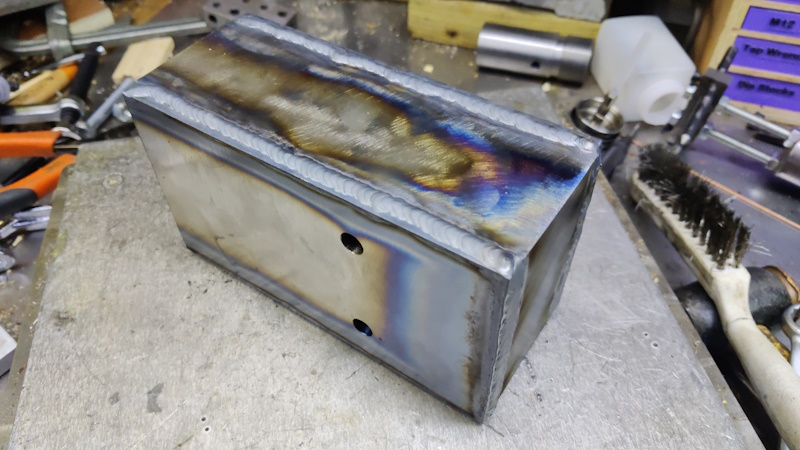
Then, after a quick touch-up with a flap disc, the front and rear faces were welded on:
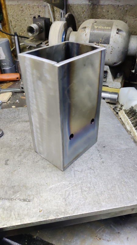
Once it had mostly cooled down, the angry grinder came out one more time to clean up the welded surfaces:
Sorry for the out-of-focus photo.
That's it for now. The next job on the headstock will be the slightly daunting task of boring the holes for the bearings and figuring out how to retain said bearings in the headstock.
My current plan is to make some aluminium retaining pieces that go over the bearings on the inside of the headstock and screw to the front and rear faces. With one holding each bearing, there should be no way for the bearings to shift. The spindle shouldn't come off the bearings (as they were an interference fit), but I'll add a nut to the back of the spindle just to be sure.
Page 6 of 43
This website is free and ad-free, but costs me money to run. If you'd like to support this site, please consider making a small donation or sending me a message to let me know what you liked or found useful.

 Return to main project page