Woodturning Lathe Build Process
Page 7 of 43
Posted 13th February 2024
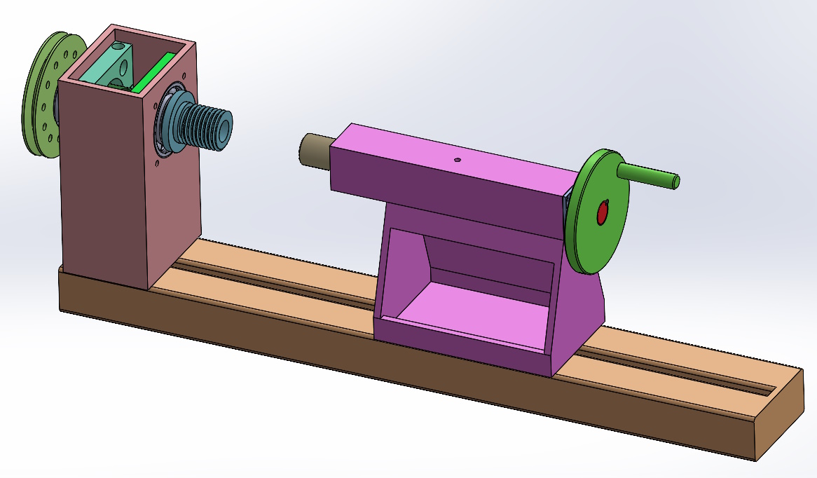
After getting a few comments asking about what I was expecting the lathe to look like once finished (answer: I'm not really sure as I'm making it up as I go along), I thought it probably would be a good idea to do a CAD model of the bits I've made so far and use that model to design some of the other bits I need to make.
I'd avoided a CAD model thus far as I'm constraining myself to use stuff that I've got lying around. Designing stuff entirely in CAD runs the risk of using stock sizes or bearings that I don't have. However, I've got far enough through the build that a lot of the major components are built, so if I work around those components, I can knock up a CAD model and hopefully won't end up designing anything that I can't then make.
With that in mind, a bit of CAD time came up with this model of the headstock and tailstock:
The triangular-ish frame underneath the square-section tailstock body is very much in question: I doubt it'll look like that in the end. However, I wanted something for the model not to look like the tailstock was floating in space.
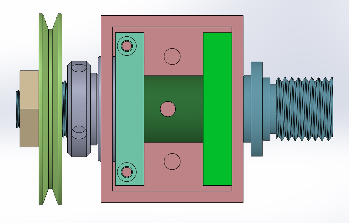
This is a top view of the headstock:
The silvery "nut" on the left holds the bearings onto the spindle (not that I think there's much chance of them coming off). The sandy coloured nut on the far left holds the pulley onto the spindle. The hole through the middle of the spindle is a new addition (i.e. I still need to drill it!) - that's there so I can shove a tommy bar through the hole when I'm tightening the nuts or a chuck onto the spindle.
The two green plates (which will be aluminium) hold the bearings (and hence the spindle) into the headstock. The right-hand plate will be permanently fixed to the headstock: the through hole will be big enough to allow the smaller bearing all the way through, but small enough to stop the bigger bearing from passing. It'll stop the spindle from moving to the left.
The left-hand green plate will be made in two pieces (hence the counterbored holes in the top to hold the pieces together). The bottom half will be dropped into the headstock before fitting the spindle and then lifted up and screwed to the top half. It's deliberately designed not to be flush with the headstock face (i.e. there's a gap on the left) so that tightening up the screws that will hold it into the headstock will apply a bit of pre-load to the bearings (which might or might not be a good thing: I don't really know anything about bearings). The left-hand green plate will stop the spindle from moving to the right, so the two plates should hold the spindle in the headstock.
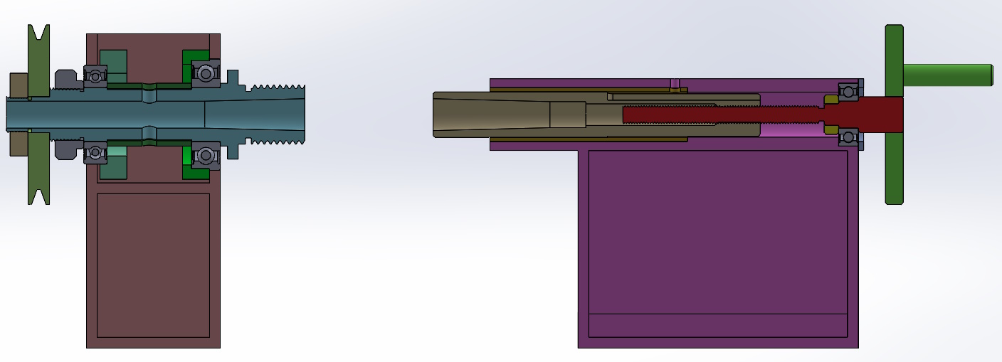
This is a cross-section of the whole model:
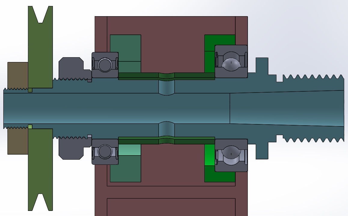
This is a cross-section of the headstock, which perhaps shows the retention of the bearings a little better:
The eagle-eyed among you will note that I've alternated between modelled threads (e.g. on the spindle) and "cosmetic threads" (on the nuts). Normal practice in CAD modelling is to use cosmetic threads, but I wanted to have the chuck thread modelled so I thought I might as well model all the threads on that part.
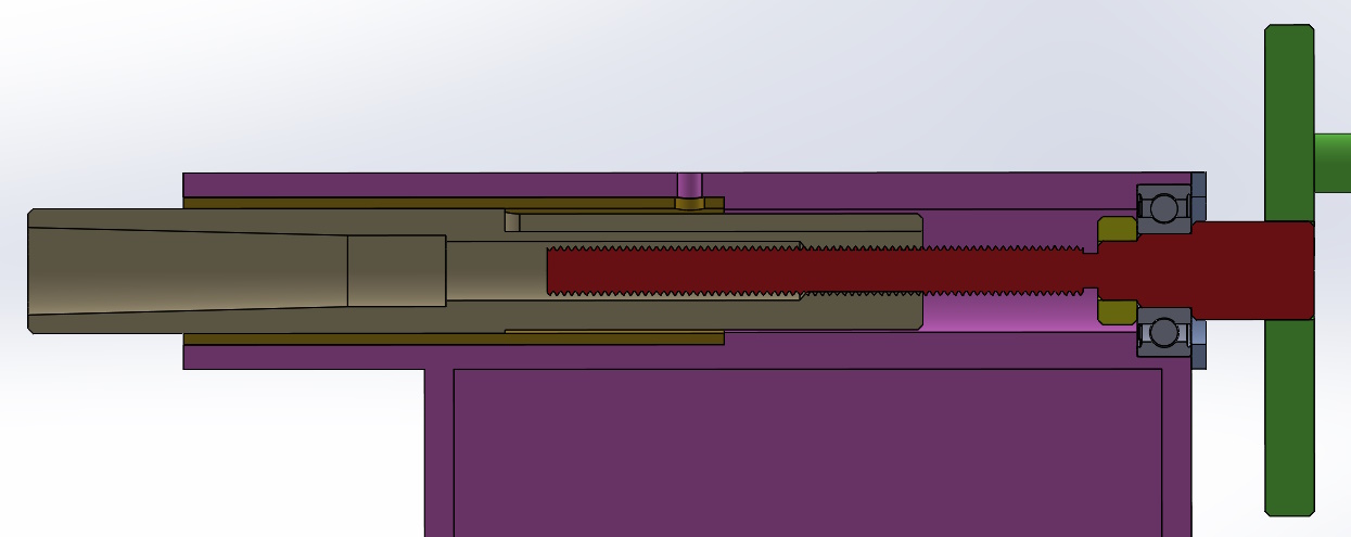
This is a cross-section of the tailstock:
The tailstock spindle (or whatever you'd call it) rides in a brass bush. The reason for that brass bush is that I figured it would be a lot easier to machine an accurate bore in a relatively short length of (nice to machine) brass bar (which will fit into the headstock) than in a very long overhanging bit of EN3B. In the top of the tailstock spindle, there's a slot (which I haven't machined yet) for an anti-rotation screw - this screw will be inserted into the top of the tailstock through the hole you can see in the middle of the image.
The threaded tailstock screw will have an M10 left-hand thread machined along most of its length. I don't have an M10 left-hand die, so I'll have to cut that long thread on the lathe. Turning the hand-wheel clockwise will make the tailstock spindle thing extend. Turning it anticlockwise will make the tailstock spindle retract and when it is fully retracted, the end of the tailstock screw should push on the end of the Morse Taper tool and make it pop out of the tailstock.
It undoubtedly would have been better to use a trapezoidal thread on the tailstock, but I don't have any suitable taps so the M10 thread will have to do.
There's a bearing in the right-hand end of the tailstock. That's probably gratuitous for a tailstock screw, but I've got one of an appropriate size, so why not? I'll be machining the pocket for the bearing with a different set-up to the other bore, but I don't think the concentricity of the screw thread is that critical, so I think it'll be okay (famous last words!)
Page 7 of 43
This website is free and ad-free, but costs me money to run. If you'd like to support this site, please consider making a small donation or sending me a message to let me know what you liked or found useful.

 Return to main project page