Woodturning Lathe Build Process
Page 8 of 43
Posted 15th February 2024
I had a couple of hours free this evening so I thought I'd get one with one of the more daunting tasks of this build: boring the bearing holes in the headstock. I started by marking the intended location of the shaft with a centre punch. This should be 130 mm above the base and in the centre of the headstock, but it's not that critical, so I didn't worry too much about precision.
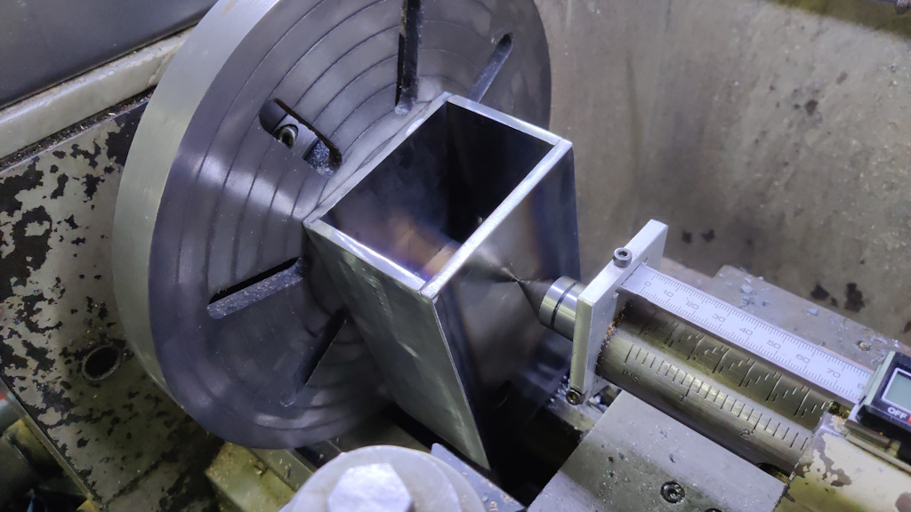
With the centre punch marked, I mounted the headstock onto the faceplate of my lathe, using the holes I drilled before welding the headstock together: the holes were positioned to be in line with the slots in the faceplate for just this reason. I then mounted the headstock on the lathe and used a dead centre in the tailstock to get the centre punch mark roughly on centre (again: I'm not too worried about precision here so I didn't bother with a dial indicator).
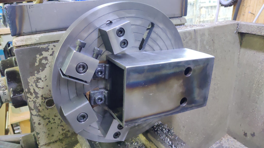
As you can possibly see from the picture, one of the reasons I chose a 130 mm centre height is that if I had gone any higher, I wouldn't have been able to swing the headstock on the face plate and would have had to find an alternative way of boring the bearing holes (e.g. line boring with a between centres boring bar, which I would have had to make).
After tightening the two M10 screws so that it would stay put, I added a couple of extra toe clamps on the top end of the headstock and also clamped some extra lumps of steel to the faceplate (actually my high profile clamps, but only because they were convenient, reasonably heavy and had holes through them that could be used for mounting). Those lumps of steel are there to make it more balanced:
It still isn't perfectly balanced, but it seems good enough as long as the lathe runs relatively slowly (I ran it at 120 rpm).
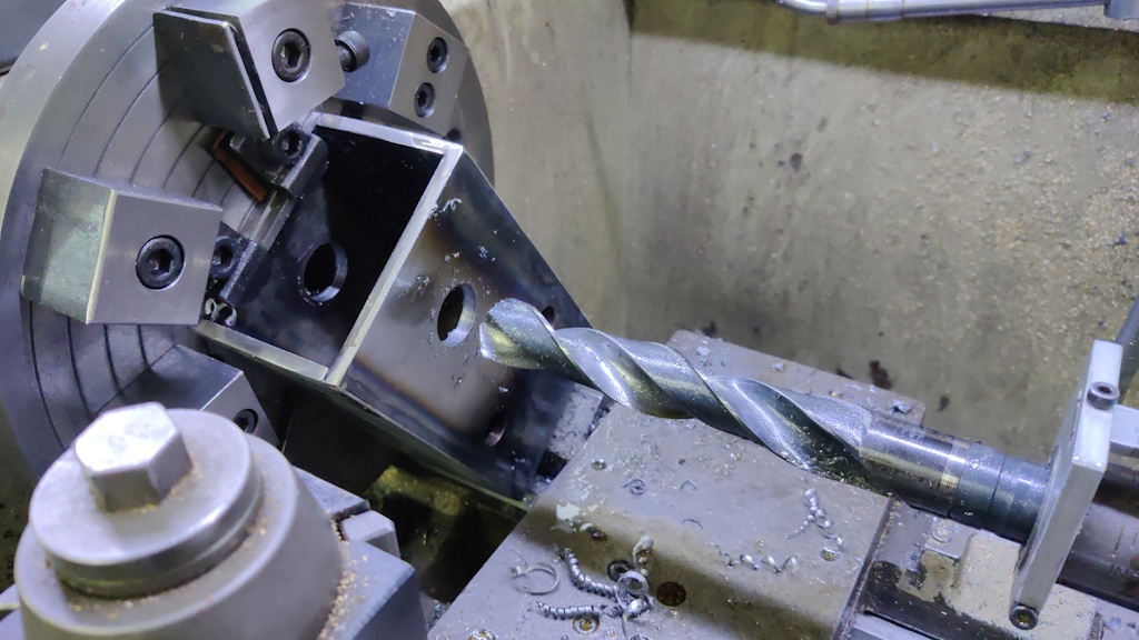
With the headstock on the faceplate, it was then another case of working up through the drills to 25 mm:
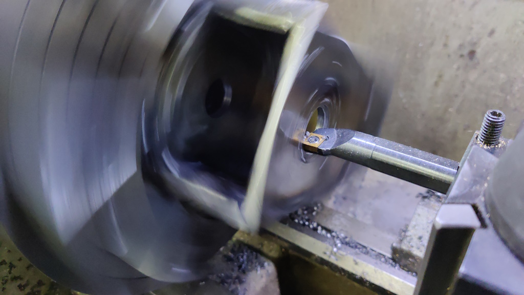
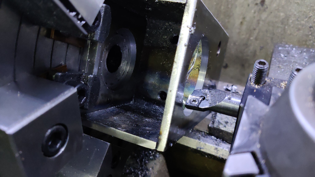
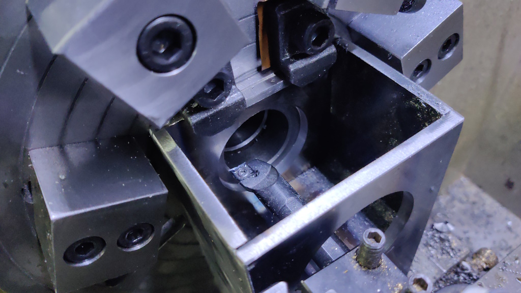
Then using a boring bar to bring the bores up to about 0.5 mm under size (54.5 mm for the rear bearing and 61.5 mm for the front bearing):
Just for fun, I recorded a short video of the rough boring process:
Once both bores were 0.5 mm under size, I swapped to a polished (CCGT) insert and took very light passes, focusing first on the larger front bearing...
... and then the smaller rear bearing:
I don't have a micrometer that's big enough for these sizes of bearings, so I got close using a telescopic bore gauge and some digital calipers and then I crept up on the final size testing with the bearing after each cut. I had the top-slide set at about 6°, so the last few cuts were made by retracting it slightly and taking advantage of the 10:1 movement ratio.
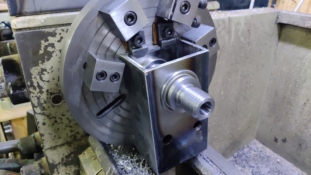
Once I was happy with both bores, I did a test fit in situ...
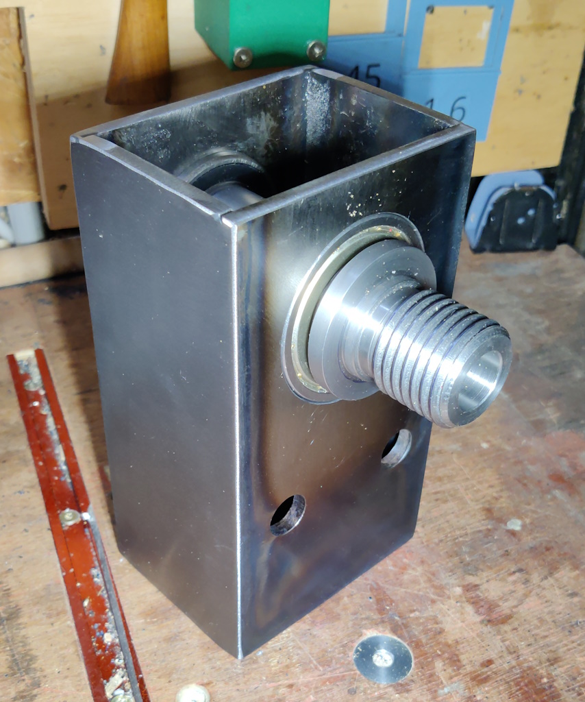
...and then removed it from the lathe and pushed the front bearing all the way home.
It's a fairly snug fit, but not that hard to push in and out of the bore with some fairly aggressive finger pressure, which is what I was aiming for (rightly or wrongly!) so I'm quite pleased with how that went all things considered.
Page 8 of 43
This website is free and ad-free, but costs me money to run. If you'd like to support this site, please consider making a small donation or sending me a message to let me know what you liked or found useful.

 Return to main project page