Travel Tool Chest & Workbench Build Process
Page 90 of 144
Posted 1st September 2023
If you cast your mind back to this post, you might remember that I'd found that the angle I put on the top of the planing stops (to help pull the wood down) meant that the back edge was a bit high when planing thin things. I'd been putting off dealing with that as milling steel isn't that much fun in my little mini-mill (one day I'll have enough space for something bigger!)
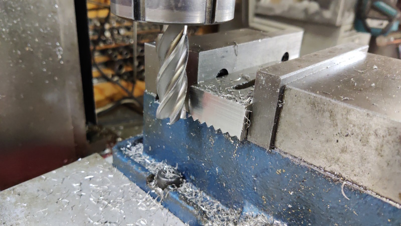
Today I decided to just get on with it and in the end it wasn't that bad at all. I used this big end mill (mainly because it was already in the chuck and I was too lazy to change it):
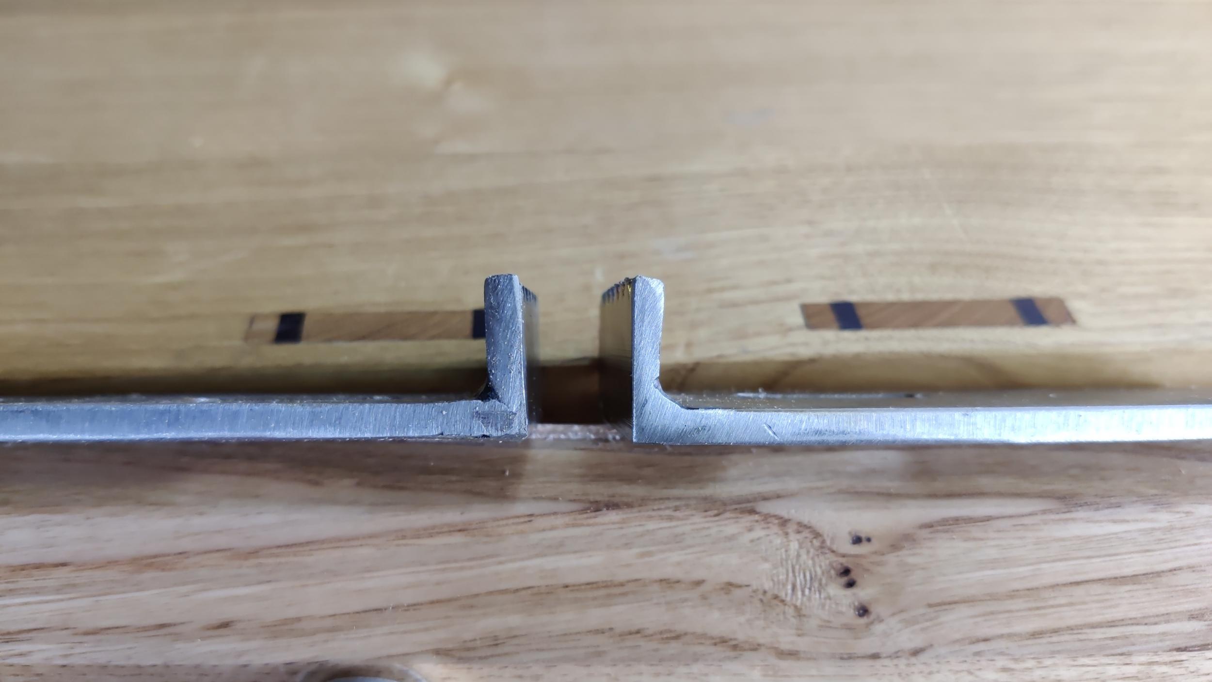
Before and after photo below. As you can see, it doesn't make a huge difference to the thickness (so no concerns about strength), but the top surface will now be parallel to the top of the chest so the plane should clear all (or none!) of the planing stop. It still has the angled teeth that will hopefully help stop the workpiece lifting.
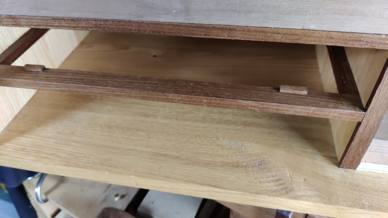
With that done a lot quicker than expected, I thought I'd move onto the next challenge. As you can see in the following photo, the drawers than run on the walnut cross pieces (I think I've called them something different every time I've mentioned them) have drawer stops set into them. The bottom drawer, however, runs directly on the chestnut base and I'd put off thinking about the drawer stops for the bottom drawer... until now...
Getting these in the right place could be considered somewhat challenging, but here's how I went about it.
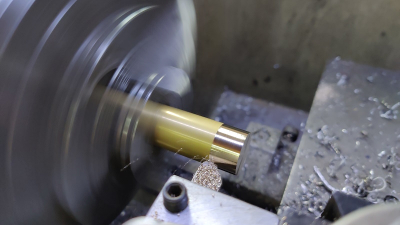
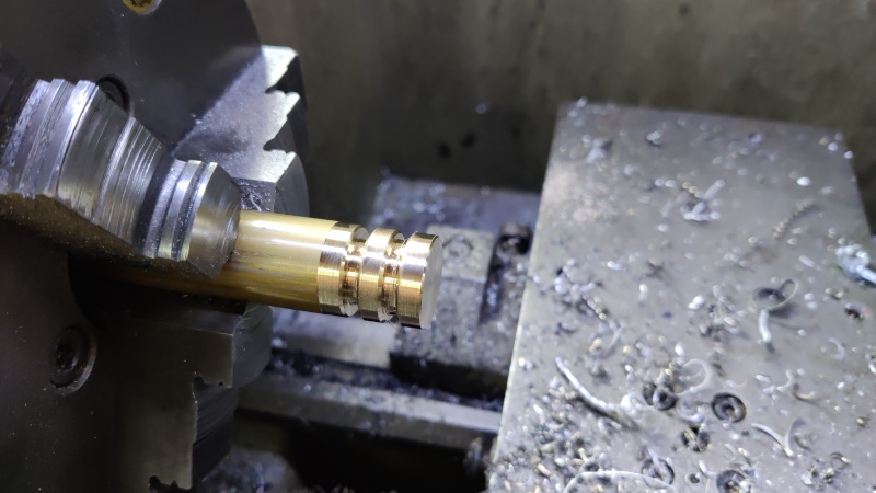
I started by putting a bit of 20 mm brass in the lathe chuck and taking a very light skim cut on the outside to prettify it:
I then cut a couple of grooves with a parting tool, mostly as a visual guide for how big I want the parts to be:
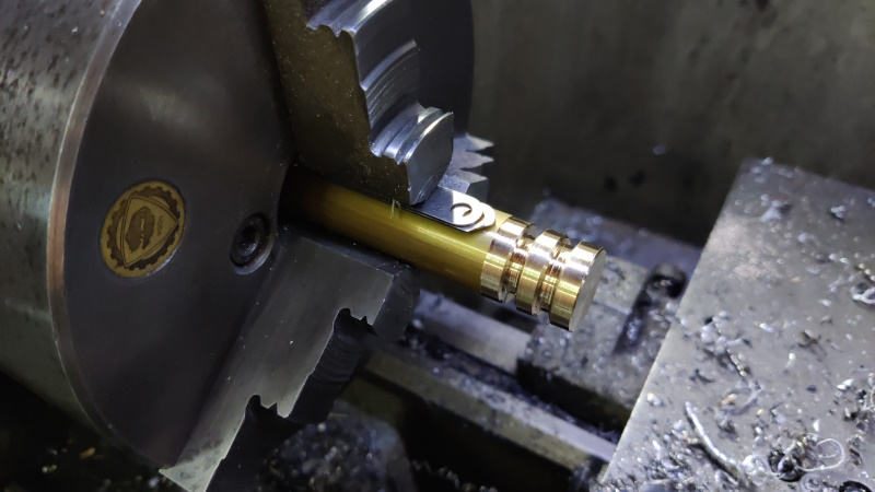
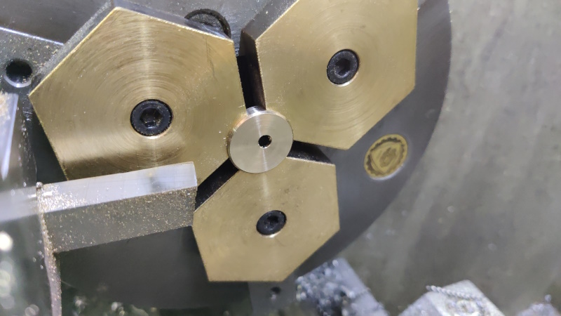
A couple of bits of feeler gauge stock (totalling 1.5 mm) were then put in between the workpiece and one of the chuck jaws:
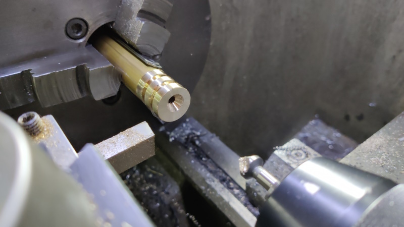
I could then drill and countersink an off-centre hole:
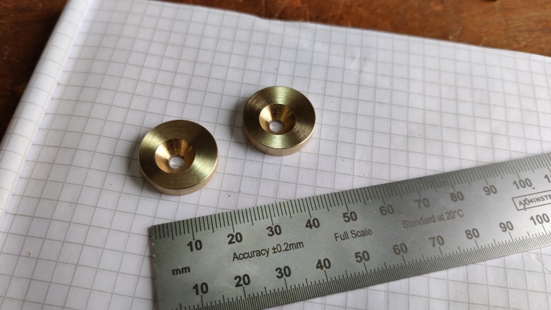
The first one was parted off in the groove line and then I faced, drilled and countersunk the second one before parting that off as well.
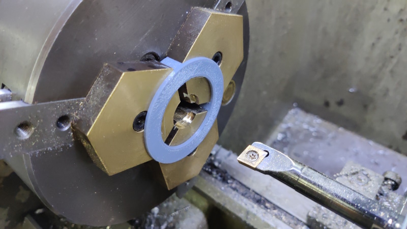
The parting tool left a rather shabby face (I've never really managed an acceptable finish straight off the parting tool), so I fitted my home-made brass soft jaws to the chuck along with a 3D printed thingamabob that allows the jaws to clamp down on something while they're machined.
A plunge cut with a 16 mm slot drill started the hole and then I could bring it to dimension with a boring bar:
The parts could then be pushed against the back of the bore in the soft jaws and I could face and chamfer them. I did both faces of each part in this set-up just to make everything tidy and consistent.
With that, my little custom cams were made:
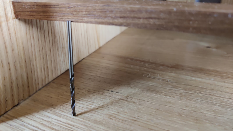
That was the easy bit. The next challenge was how to drill the pilot holes for the screws that would hold the cams in place. Not easy when the chosen drill bit is longer than the gap between the base and the first cross piece, even before you put it in a drill chuck!
Given it was only very slightly too long to fit in the gap (and given it's a 2.5 mm drill bit, which is tapping size for M3 and hence I have lots of spares), I sorted out the length by just cutting a bit off the shank with the angry grinder. Now all I needed was a zero-length drill chuck.
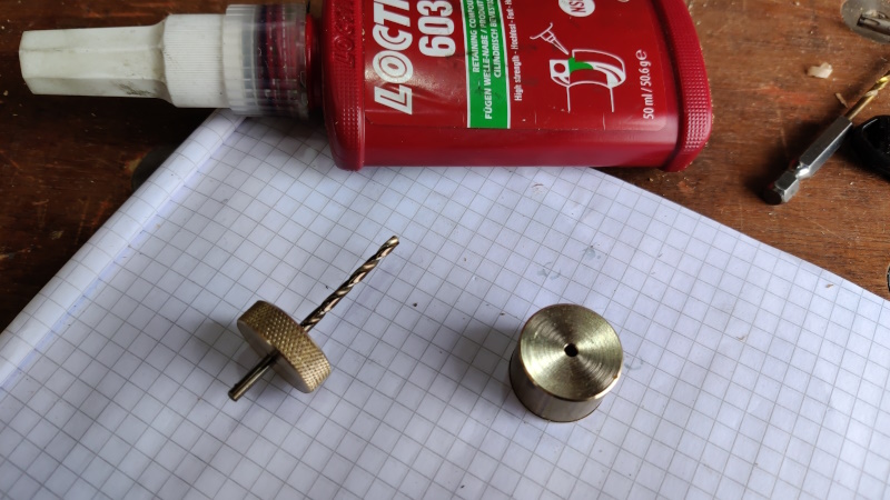
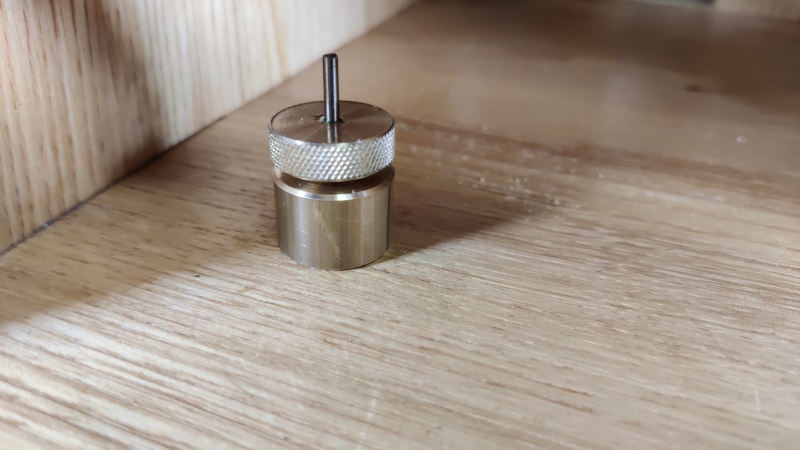
It's handy having a lathe:
The drill bit is glued into the knurled brass bit with Loctite 603; the other piece is just a plain brass piece with a 2.5 mm hole, which serves two purposes. Firstly, by holding it down to the chestnut surface, it makes sure that the drill bit goes in square. Secondly, it acts as a depth stop: when the knurled bit reaches the plain brass bit, I've drilled far enough and it's time to stop.
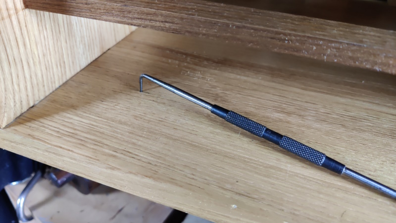
Before drilling though, an awl or a centre punch mark would be useful to get the drill going in the right place. Not a chance I'd fit either awl or centre punch in that gap, so I abused a metalwork scriber:
It was then just a case of turning the knurled ring by hand until it reached the stop:
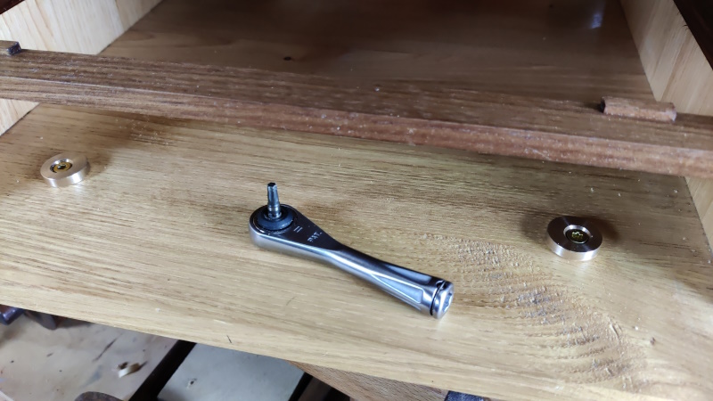
Fitting the parts was quite straightforward as I have a very handy little ratcheting bit driver.
Loosening the screws off very slightly allows the cams to rotate and, being eccentric, adjusts the exact place at which the drawer stops.
Page 90 of 144
This website is free and ad-free, but costs me money to run. If you'd like to support this site, please consider making a small donation or sending me a message to let me know what you liked or found useful.

 Return to main project page