Woodturning Lathe Build Process
Page 22 of 56
Posted 3rd March 2023
The next job to work on was the method of attaching the bed to the motor.
I've got quite a lot of 3030 t-slot extrusion. A lot of it has holes/slots in various places (most of it came out of a skip having been used and discarded), but it's still perfectly usable. This seemed a good basis for the motor mount as the t-slots give an easy method of sliding the motor back and forth to apply tension to the belt.
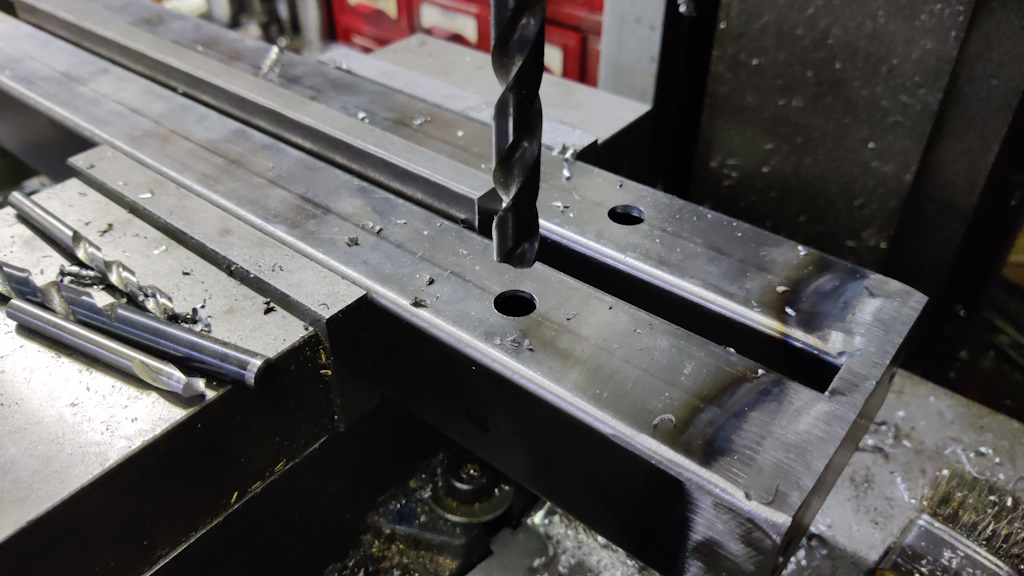
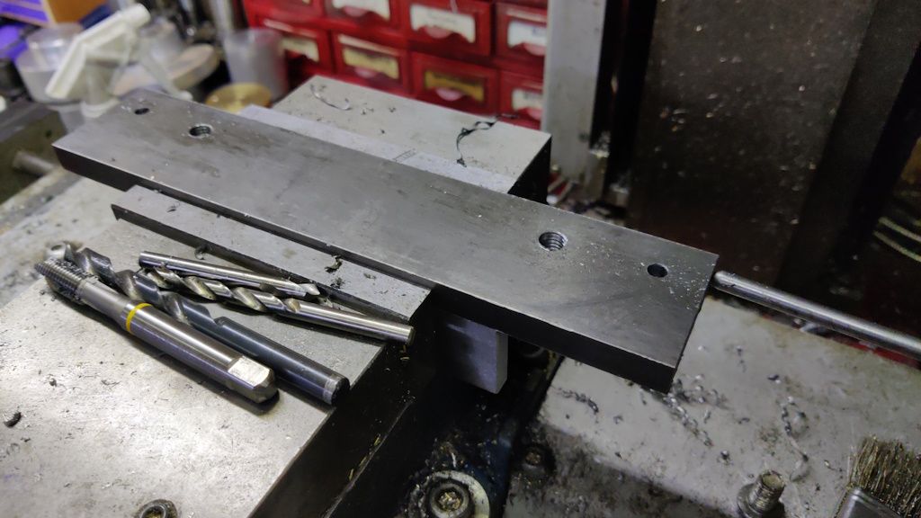
To attach to the bed, I clamped the bed in the mill vice (with some 12 mm flat bar in the gap to stop the vice from bending the bed) and drilled some holes:
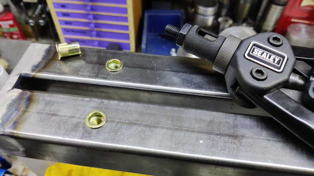
Rather than welding in some nuts (and risking distortion from the heat of welding), I decided to use M8 rivnuts for the bed attachment. These also have the advantage of being very quick to fit:
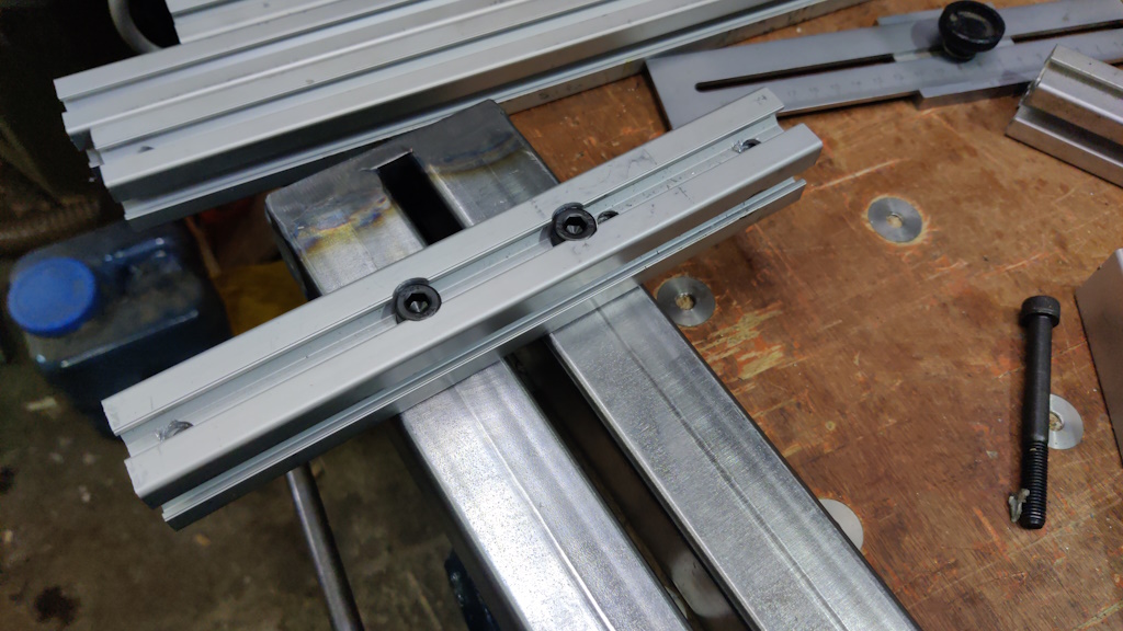
Some "feet" could be attached to the bed using those rivnuts:
There's one of these at each end of the bed. They raise the bed up by 30 mm, giving clearance for the t-nuts etc. I've spaced them 864 mm apart and drilled / counterbored some extra 8 mm holes out-board of the bed on a 192 mm pitch. Those numbers are both multiples of 96 mm, which corresponds with the dog hole pitch on my bench, so I have the option of screwing the bed down using those holes (although in practice I suspect it will be quicker to just use a couple of F-clamps).
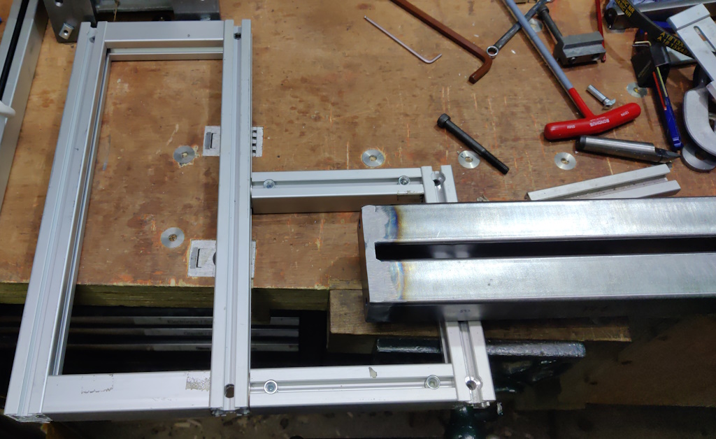
I then built a simple frame out of t-slot extrusion, using some coupling joints that came out of the skip with the extrusion:
By undoing two of the M8 grub screws that hold the frame together, the motor mount section can be easily separated from the bed section, which is important as I don't think I'd be strong enough to lift the lathe and motor in one piece (the motor is very heavy).
To attach the motor to the extrusion, I cut a couple of lengths of 12 mm × 50 mm EN3B and used the lathe to drill/tap a couple of M10 holes and drill a couple of 6 mm holes in each:
Those plates got bolted to the bottom of the motor with some short M10 cap screws and some extrusion t-nuts and M6 cap screws used to hold the motor mount plates to the extrusion:
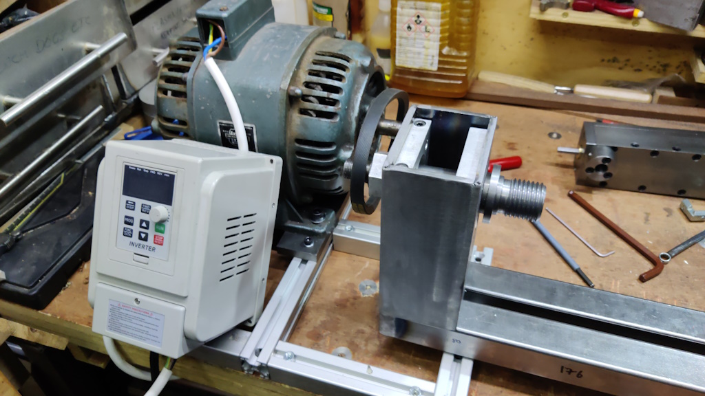
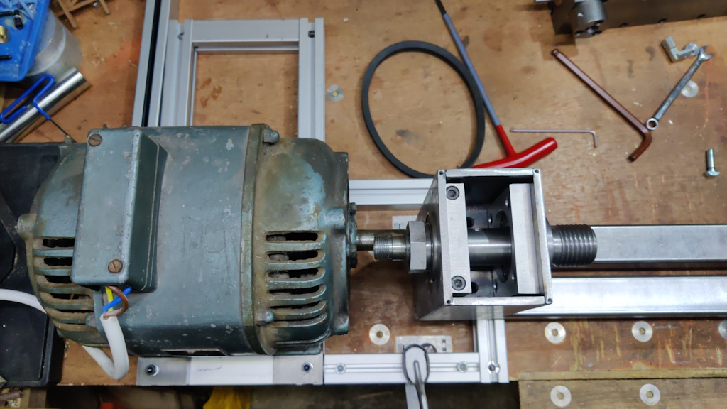
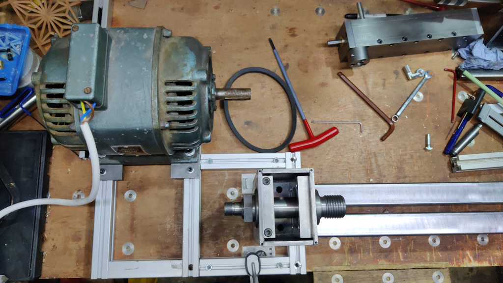
Loosening the four M6 cap screws allows the motor to slide easily back and forth on the relatively smooth surface of the aluminium extrusion. The two extremes of travel are shown in the next two photos:
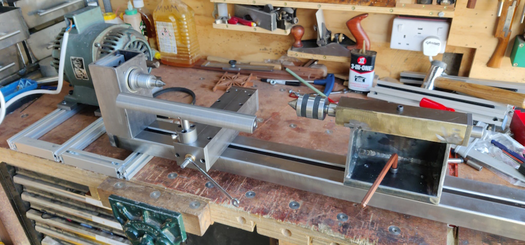
General view of everything:
With that done, I thought I'd have a go at making some pulleys (and reminding myself why I hate turning aluminium). I had thought about modifying the spindle such that the pulley mount diameter was common between the motor and the spindle, but after thinking about it more I decided not to do this. The pulley for the motor probably needs to be longer (thicker?) than the one for the spindle due to the different mounting methods. The spindle pulley will be held on using a nut; the motor has a keyway and no thread, so the pulley is best mounted with a grub screw.
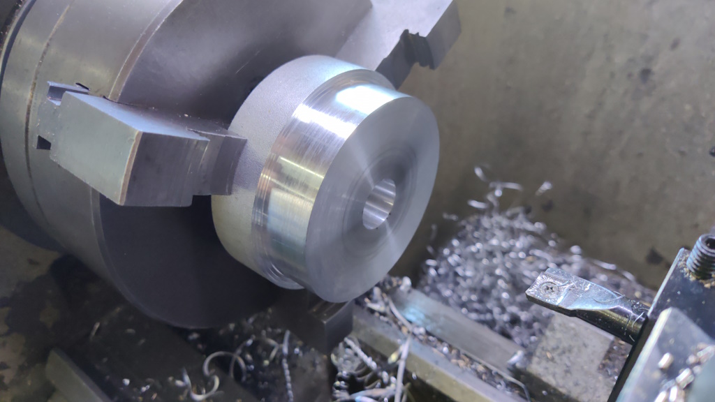
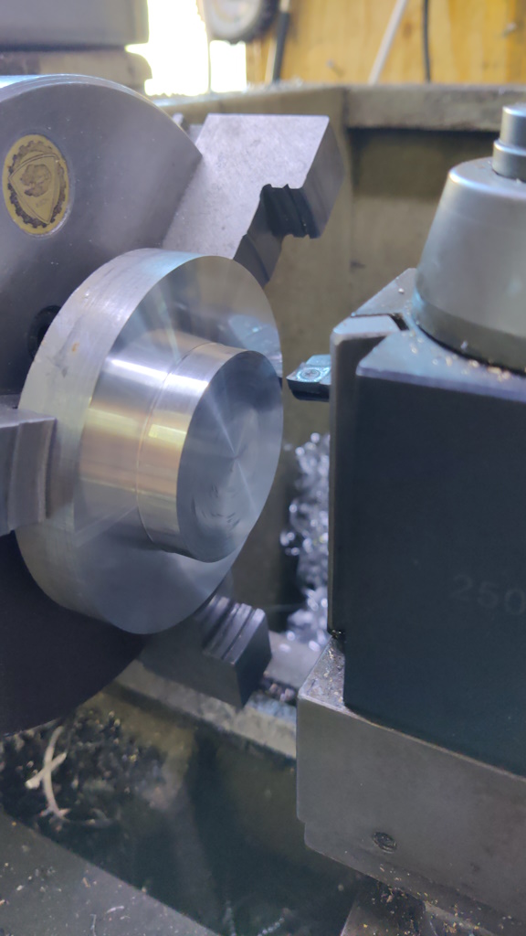
For the spindle pulley, I started with a big disk of aluminium, held in the outside jaws of the three-jaw chuck. I faced the end, skimmed the outside diameter down to 80 mm (fairly arbitrarily chosen) and drilled/bored a 20 mm hole through the middle:
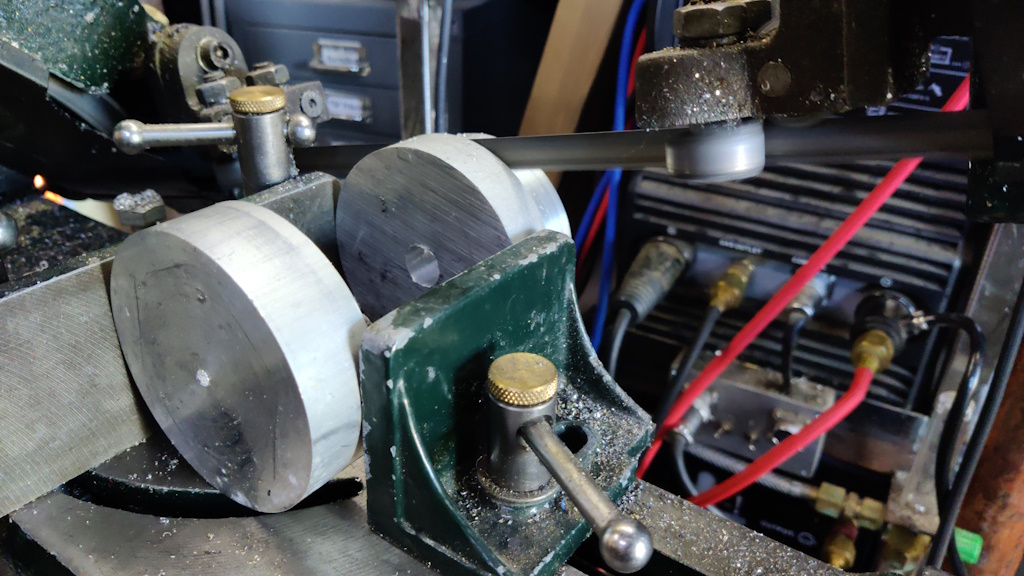
I used the bandsaw to chop it off over length:
I then faced it to length, again held in the outside jaws:
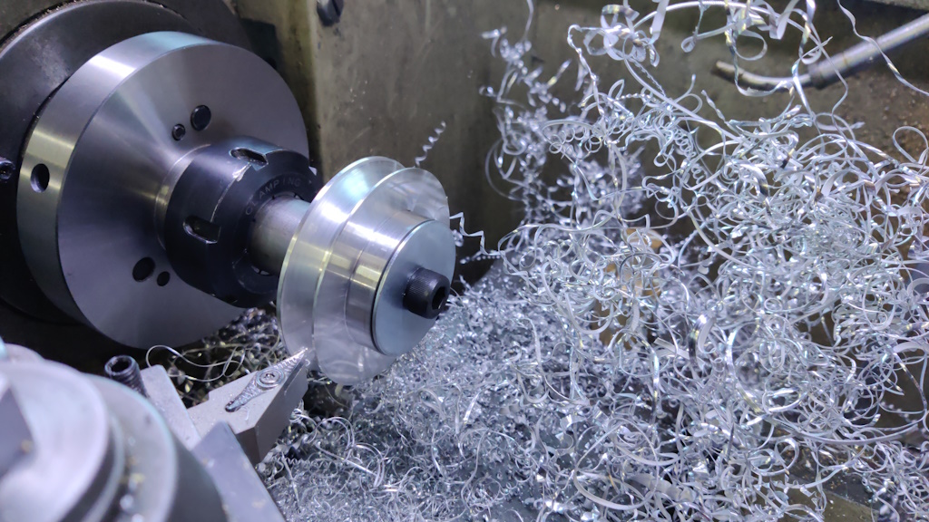
To help with shaping the pulley, I used a bit of 30 mm EN1A to make a simple mandrel, with a 20 mm outside diameter and an M10 hole through the middle. I used the collet chuck to hold the mandrel as it gives a bit more clearance for top slide rotation (and to remove the chance of accidentally hitting the spinning jaws).
I then set the top slide at 70° to the lathe axis to cut one side of the pulley shape (the drive belt I have has a 40° included angle, so 20° on each side). I then rotated the top slide and did the same for the other side of the pulley shape. I tried to get a few photos, but messed up the focus on all of them; believe it or not, this was the best:
This was what it looked like when finished:
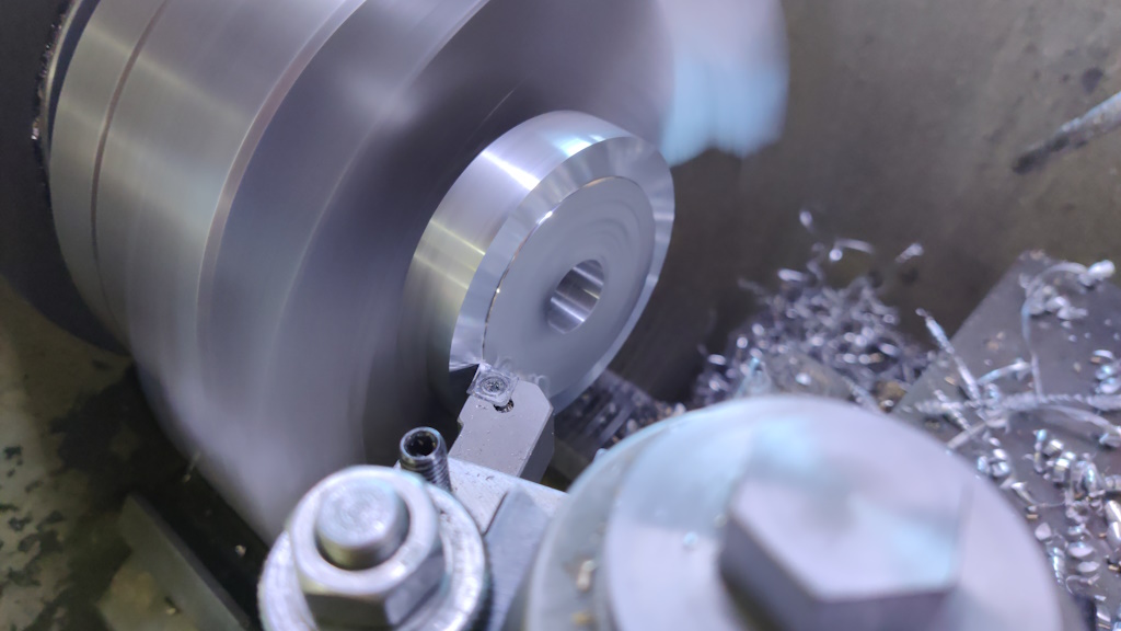
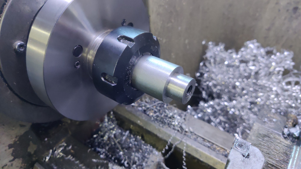
To make the motor pulley, I started with another disk of aluminium and turned a reduced diameter section (about 50 mm). This section is intended to be where the grub screw will be fitted for clamping the pulley onto the motor shaft.
Due to the overhang of the outside lathe jaws, there wasn't space for a normal tool, so I used a boring bar and turned the shape with the lathe running in reverse:
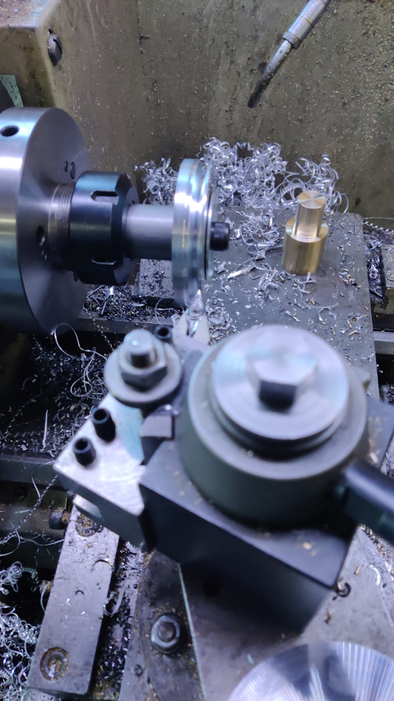
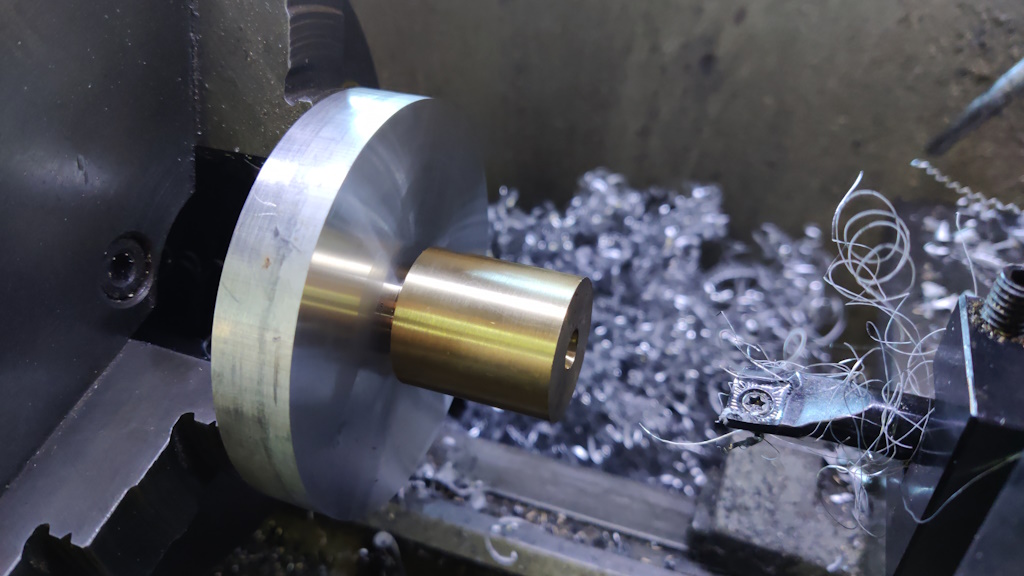
I then bored the 19.05 mm (3/4") diameter hole in the centre, using a bit of brass (that I'd previously turned to size) to check the size was (what I thought was) right:
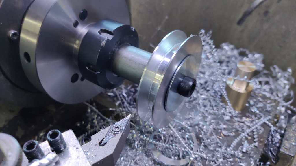
The same mandrel as before (but turned for a longer section at a smaller diameter) was used to mount the blank and I could then turn the pulley shape. This photo gives more of an idea of why I detest turning aluminium!
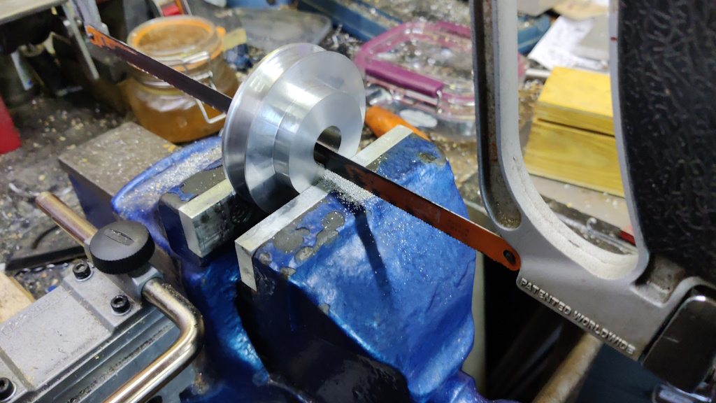
To cut the keyway, I started by feeding a hacksaw blade through the slot and then remounting it to the hacksaw frame. I could then rough out the slot:
That got finished with a lot of tedious work with a hand file.
I then had a go at fitting the pulleys. The spindle one went on very easily and was clamped in place with another nut that I made in the same way as the spindle mount nut that I described earlier (I also shortened the spindle mount nut and made a second short one as they're now being used to pre-tension the spindle bearings and hence need to lock together to hold the tension).
The motor pulley was a lot more involved. I'd measured the motor spindle near the bearing and it was 19.048 mm according to my micrometer. That corresponds fairly closely to 19.05 mm, which is 3/4", so that made sense to me and hence that's the size I made the pulley bore. When I tried to fit the pulley, it wouldn't go on.
I re-measured the motor spindle and found that (rather bizarrely in my opinion), it's 19.048 mm near the bearing, but 19.35 mm at the tip! That makes for a rather awkward situation: if I enlarge the hole to be 19.35 mm, then it might end up being very loose by the time it's pushed all the way on (although I guess the grub screw would probably deal with that issue).
I've got a 19–21 mm adjustable reamer, so I used that to gradually increase the bore diameter. I was feeling quite nervous about making it too big (I really didn't want to have to start again with this part!), so I took very light cuts and kept trying to mount it on the motor spindle. After several cuts, I found that I could "persuade" the pulley onto the motor shaft with a mallet.
It took quite a bit of persuasion to get it to seat. Sufficient persuasion that it'll need a bearing pulley to get it back off! I had intended to cross-drill and tap the hole for the grub screw after making sure that the pulley fitted over the keyway, but given how tight it is, I've decided to leave it for now.
With an 80 mm (outside) diameter motor pulley, it should be easy enough to adjust speed (if I need more range than I can get from the variable speed drive) by either fitting a bigger spindle pulley (for slower speeds and more torque) or a smaller one (for higher speeds). I'm not sure which diameter to use for the speed ratio calculation (outside of the belt, inside of the belt, middle of the belt?), but with the variable speed drive, it probably isn't that critical.
For now, I've got 80 mm outside diameter pulleys on both the motor and the spindle, so the speeds should match.
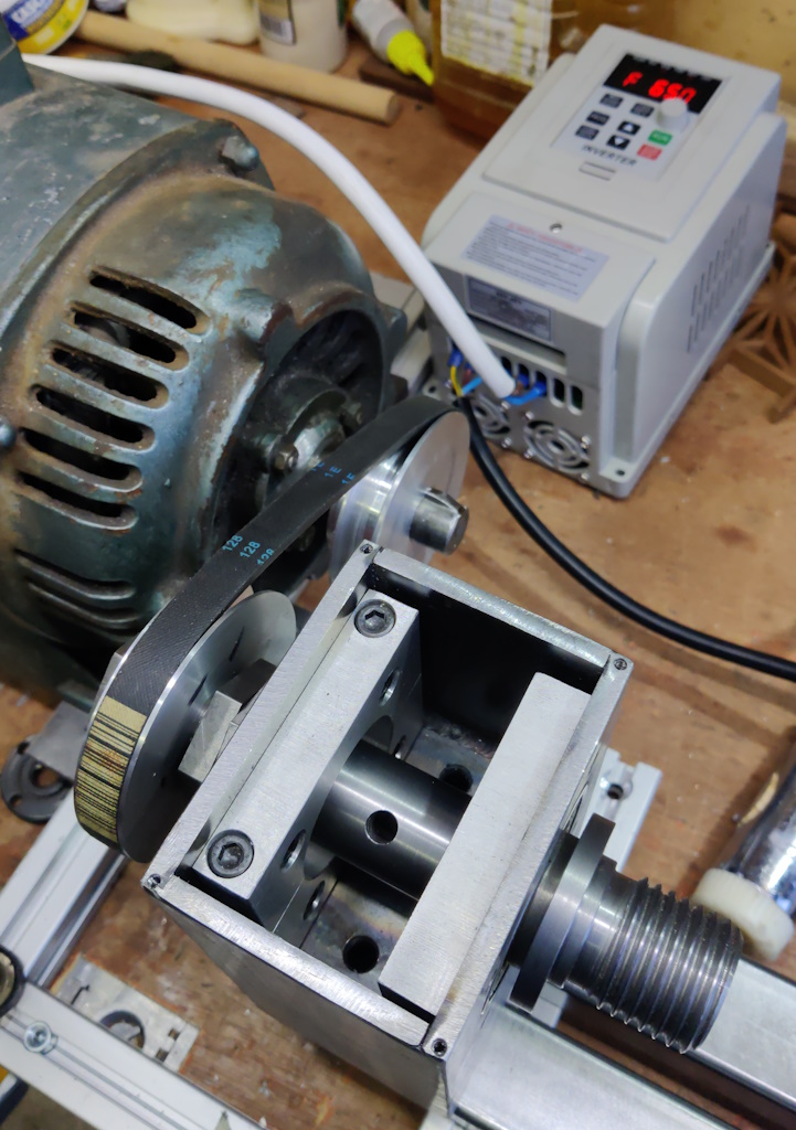
With the pulleys made and fitted, I could fit the drive belt and slide the motor back to apply some belt tension:
I couldn't resist a quick spin test:
It's feeling much closer to being a lathe now that the spindle has been run, but there are still quite a lot of pieces to make before I can start cutting wood. My hope is that I'll be able to at least do some trial cuts by the end of next weekend, but we'll see what happens.
Page 22 of 56
This website is free and ad-free, but costs me money to run. If you'd like to support this site, please consider making a small donation or sending me a message to let me know what you liked or found useful.

 Return to main project page