Dog Clutch


A dog-clutch makes threading much easier: no messing around with thread-dial indicators and, most importantly, no worrying over whether you can stop the machine before it reaches the end of the threadable area. My design is based on John Moran's one, described in detail on his website. The clutch itself is very similar to John's design; the only significant difference being that I converted it to metric (although as the lathe is inherently a metric machine, most of the dimensions shown by John are simply an imperial conversion of a metric measurement: e.g. 0.276" is the imperial equivalent of 7 mm). Also visible in the photo above is my simple threading banjo and my simple spindle extension.
Please note that, after about a year or use, I elected to remove the dog clutch from the lathe. You can read more about my reasons for this in the update at the bottom of the page.
Clutch

This photo shows all of the parts that make up the clutch mechanism. Running from left to right along the top, these are: an M5 gear retension screw and washer, gear A from the selected change-gears, the idler, the clutch itself, the main shaft, the transfer gear and the circlip that holds the transfer gear in place. Beneath these in the photo are the modified mount, the shift lever, a tap-washer that is used as a rubber spacer and the support screws that replace the M5 cap screws that hold the mount on the standard machine.
The idler is turned from 1/2" mild steel. For most of its length it has an outer diameter of 12 mm, but a 1 mm long section is left at 1/2" diameter 5 mm from the inner end. the total length is 14 mm and it has a 7 mm hole all the way through. The keyway is 3 mm but doesn't reach the ends of the idler to ensure that the key doesn't eject itself from the idler.
The clutch is turned from 20 mm mild steel. I originally made this from brass (as per John's website), but I think I made the inner end too thin and it broke fairly soon after starting to use it, so I remade it from steel and thickened up the inner end. It is 5 mm long in total and has a 1.6 mm (1/16") groove cut 1.5 mm from the inner end. The groove is 1 mm deep, so reduces the outer diameter to 18 mm in this section. The clutch has a 12.2 mm bore and 3 mm keyway.
The main shaft is, in total, 41.5 mm long. The right-hand end is 7 mm diameter and 7 mm long. The keyed section is 12 mm diameter and 11 mm long with a 0.5 mm deep groove a little over 8 mm from the left-hand side as shown in the picture. This is for the circlip that holds the transfer gear in place. The central body section is 15 mm diameter, 6.5 mm long. Immediately to the left of the central body section is a 2.7 mm long 12 mm diameter section with a 3 mm hole cross-drilled to just over half-depth. A piece of 3 mm HSS tool-bit is used as the dog and is glued into this hole. The shaft on the left (on which the idler runs) is 6.95 mm diameter and 14 mm long. There is an M5 hole tapped in the end for the gear retension screw.
The shift lever is made from 3.2 mm aluminium plate. The overall size is 92.5 mm × 44 mm, although the dimensions are certainly not critical. The large hole in the centre is 22 mm diameter, but has been enlarged lengthwise to 28 mm long. The pins that engage with the groove in the clutch are 1.2 mm piano wire, as described on John's site.


The clutch mechanism is shown assembled above. On the left, the clutch is disengaged and the transfer-gear can rotate independently of gear A. On the right, the clutch has been engaged and the two gears are now locked together.
This animation of the dog-clutch operation (created with v0.15 of the free, but not yet complete, 3D CAD application FreeCAD) may help with understanding how this works. It will need a relatively modern web-browser to work (if you have problems, try Google Chrome or Mozilla Firefox); if you can't make it work you can download it here and play it with something like the VLC media player.
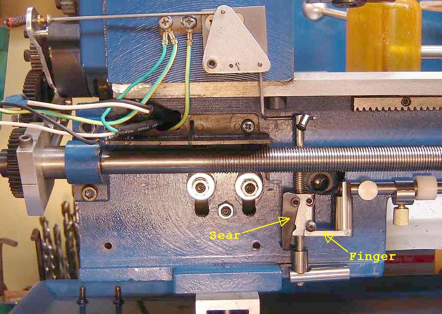
Trigger Mechanism
I'll confess, I looked at the pictures of John's trigger mechanism and couldn't make head nor tail of them, so I decided to try something simple and see if that worked (which it did!)
This picture shows the main part of the mechanism that I built. All of these parts were made from bits from my scrap bin, so dimensions were chosen accordingly. An 8 mm shaft is mounted in two simple pillow-blocks (one can be seen in the bottom right of the picture above) and runs across the whole length of the lathe. This shaft is threaded M8 on both ends. On the right hand end, this thread is just used for a (lightly loaded) spring and nut to hold the shaft in the engaged position. On the left-hand end of the shaft is a block of 19 mm × 20 mm × 12 mm mild steel with a 10 mm cut-out at the top. It is held onto the threaded portion of the shaft with two M8 nuts. This can be seen in the right-hand picture below:


A 9 mm thick 38 mm diameter steel disc is used to translate the horizontal movement of the shaft into a vertical movement of a piece of 3 mm mild steel. As the linkage (in the right-hand photo) is moved to the left, the disc rotates clockwise and pulls the 3 mm wire downwards. The disc has a 10.5 mm hole through the middle (the dimension was chosen because I had a piece of 38 mm steel with a 10.5 mm hole in the middle already!). There are two other holes in the disc, at 90° from one-another: one is tapped M5, the other M6. The M5 hole (on the right of the photo) holds a short piece of 6 mm mild steel, with a section reduced to 5 mm and tapped M5. It is cross-drilled 3 mm for the linking wire, which has an M3 thread cut on the end for two nuts. It is fitted into the disc very loosely so it can turn freely as the disc rotates.


In these images, the disc can be seen more clearly. The left-hand image shows the 6 mm connecting piece loosely fitted on the right-hand side of the image. On the right-hand side of the right-hand photo, you can see a piece of 10 mm steel attached to the disc with an M6 cap-screw which has had the head reduced in diameter to less than 10 mm. This engages with the slot in the component fitted to the main shaft. The shaft that the disc rotates on is 15 mm diameter 20 mm long. A 9 mm long section is reduced to 10.5 mm for the disc to run on. The hole through the middle is 6 mm for the M6 mounting screw. The length of the shaft was chosen such that the 3 mm wire clears the lead-screw.

The second part of the trigger mechanism is a piece of 3.2 mm aluminium saved from the scrap bin. It pivots on an M6 screw and has two 4 mm holes (one of which is 45 mm from the pivot and the other is 15 mm from the pivot) for the 3 mm wires that connect the parts of the trigger mechanism together.


The sliding adjustment piece shown in the left-hand photo is 20 mm diameter and 40 mm long. It has an 8 mm hole drilled through for the shaft and two M6 threaded holes cross-drilled at 10 mm and 25 mm from the left-hand end. It is used to set the position at which the dog-clutch disengages. To actuate this sliding adjustment piece, a large block of steel is bolted to the bottom of the carriage such that the carriage will push the adjustment piece to the left and disengage the clutch.
Initially like John, I found that this dog clutch makes threading considerably easier and is extremely repeatable. However, my "trigger" mechanism isn't a true trigger and I suspect that John's mechanism is a much better design.
Update - Dog Clutch Removed
About a year or so after building and fitting the dog clutch, I finally removed it from the mini-lathe. Due to the small size of the components in the clutch itself, it had needed repair a couple of times in that period. Also in that period I'd found a much better way of threading. I now do almost all of my threading with the tool mounted upside-down in the tool-post and the lathe running backwards (don't do this if you have a threaded chuck mount). In this configuration, the tool is moving away from the headstock as it cuts and you have all the time you need to disengage the leadscrew when the tool has run off the end of the workpiece.
The only time I now cut threads with the lathe running forwards is when cutting imperial threads (as the leadscrew needs to remain engaged all the time). I do my best to avoid anything imperial, so this doesn't happen often.
This website is free and ad-free, but costs me money to run. If you'd like to support this site, please consider making a small donation or sending me a message to let me know what you liked or found useful.